

.svg)
industry insights
Featured Articles
Is Utility Mapping Worth the Cost?
Why Do You Need Updated As-Builts on Your Next Project?
industry insights
GPRS Helps an Austin Apartment Complex Avoid Disaster by Locating Potential Voids
The empty areas underneath slab-on-grade concrete and/or pockets of air within concrete slabs are known as voids. They can form due to soil erosion, poor installation or compaction, animals digging, or trapped air.
Concrete voids can lead to significant damage. Unaddressed concrete voids lead to reduced load-bearing capacity, safety hazards as the concrete shifts and sinks, water damage and leaks, or complete structural failure.
The High Point Reserve apartment complex in Austin, Texas was experiencing signs of concrete voids. They noticed their foundation was sagging and water was leaking.
The complex took immediate action and hired the general contractors the Journeyman Group to address the problem. The GCs then tasked GPRS Senior Project Manager Daniel Reis with scanning the concrete slabs to identify any potential voids.
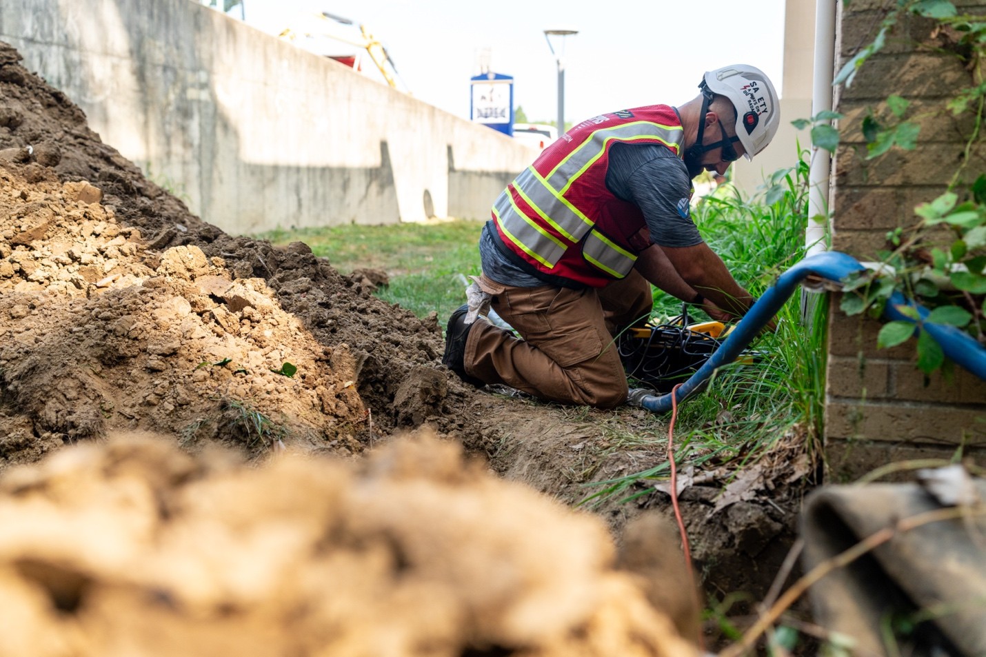
When scanning concrete slabs, GPRS PMs utilize ground penetrating radar (GPR). They analyze the results with an expertly trained eye to map out any conduit, rebar, post tension cables, or, in this case, potential voids.
Since 2017, our Project Managers have maintained a <0.2% at-fault incident rate on concrete scanning jobs, so Journeyman and the stakeholders could rely on Reis’ results.
When he was first called to the site, the scope of work was scanning a walkway running some of the units. Based on what his scans were showing him, he believed there was a larger issue at play.
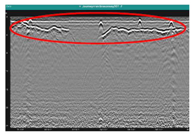
“Originally, the job was scheduled for a half day and the note section said that they were hoping we could identify potential voids,” Reis explained. “They had just a couple of areas of concern that they wanted me to check out. When I got toward their area of concern, it made me concerned. I saw the data and I told the client, “I can definitely see through the slab - this area is concerning.’”
After scanning other areas of concern over the next hour and talking with Area Manager Ryan Dennis about the situation, Reis went back to the client to deliver his initial findings and gather more information on the site.
“I then talked to the on-site contact and found out that they had quite a few more areas that were concerning to them,” Reis explained. “So, I gave them my business card and I said, ‘Whenever you're ready to get these scanned, we’ll get you guys on my schedule.’ And the on-site client said, ‘Yeah, let's go ahead and do that.’”
The scope of work expanded from a half day to multiple trips over two weeks. Reis scanned rooms predominately on the first floor and other breezeways in multiple buildings during his visits.
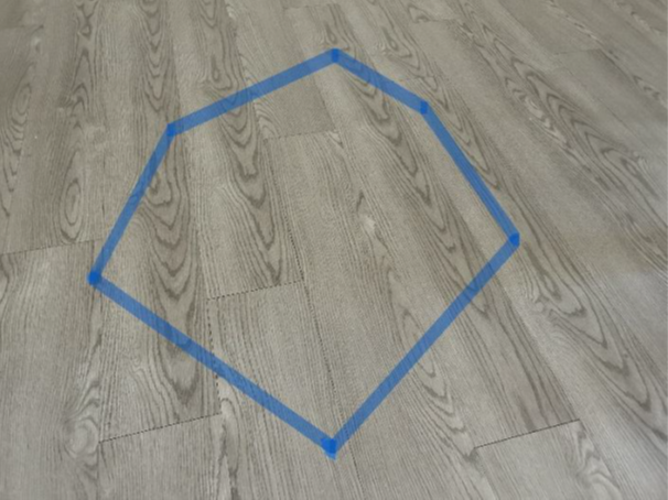
Since the apartment complex had current residents, the owners didn’t want Reis’ findings marked with spray paint or chalk to avoid potential panic about the condition of the tenants’ homes. Seeing random red or black markings on your living room or kitchen floor certainly would raise some eyebrows. Reis instead marked the areas with potential voids using tape that was easily removable once they took photos and talked with the site contact.
Each time Reis conducted scans at the complex, he presented the Journeyman Group with a formal report along with the typical Job Summary Report (JSR). Every job conducted by GPRS features a JSR, which is exactly that – a summary of the job for the client to reference. A formal report gives the client a more in-depth report on our PM's findings in specific areas that includes GPR data screen shots, photos, and a map of our findings.
It is important to note that GPRS’ non-destructive concrete scanning methods can only identify potential voids, as verifying a concrete void requires additional destructive testing practices like concrete coring.
Reis' contact with the Journeyman Group has since reached out to let him know his scans have been very helpful in the planning process. They have also asked him to come back and scan the remaining buildings to ensure they have complete visualization of the site.
If your site is experiencing signs of concrete voids, don’t wait until it gets worse. Our team of concrete scanning professionals is happy to help identify where potential voids may be hiding.
FREQUENTLY ASKED QUESTIONS
How does ground penetrating radar detect potential voids?
When using GPR to investigate concrete, the device sends radio signals into the slab and reads the “bounces” when the wave encounters an object. These bounces appear as hyperbolas that our expertly trained Project Managers can read like a book.
From a potential void to a PT cable, each one has its own signal pattern that PMs use to decipher what is within the concrete slab. Schedule concrete scanning services here.
Can GPR determine the difference between rebar and electrical conduit?
Ground penetrating radar (GPR) can accurately differentiate between rebar and electrical conduit in most cases. We have an extremely high success rate in identifying electrical lines in supported slabs or slabs-on-grade before saw cutting or core drilling.
Additionally, GPRS can use electromagnetic (EM) locators to determine the location of conduits in the concrete. If we can transmit a signal onto the metal conduit, we can locate it with pinpoint accuracy. We can also find the conduit passively if a live electrical current runs through it.
The combined use of GPR and EM locating allows us to provide industry-leading conduit locating services. Schedule concrete scanning services here.
How are concrete scanning results from GPRS marked on site?
GPRS Project Managers use anything from spray paint, chalk, markers, and tape to mark their findings on concrete slabs. They also can mark their findings on temporary floor protection boards that are placed on top of the slabs to ensure they don’t leave markings in public, high-traffic spaces.
There is not a color code when identifying concrete obstructions like post tension cables, rebar, or conduit. So, we created one: the Green Box Guarantee. When a GPRS Project Manager marks a section of concrete with a green box, that means it is clear of obstructions.
Schedule concrete scanning services here.
What is SIM?
Subsurface Investigation Methodology (SIM) is a standard operating procedure and set of professional specifications that work as a guide for utility locating experts when scanning for buried utility lines. All GPRS Project Managers are required to achieve SIM 101 certification, which requires 80 hours of hands-on training in a classroom setting and 320 hours of mentorship in the field. For reference, the American Society for Nondestructive Testing’s (ASNT) minimum training recommendation includes eight hours for training and 60 hours practicing GPR to achieve NDT Level 1 certification in ground penetrating radar (GPR) scanning.
SIM requires the use of multiple, complementary technologies, like GPR scanning and electromagnetic (EM) locating, when locating buried utilities or scanning a concrete slab.
What is Geotechnical Engineering
What Is Geotechnical Engineering?
Every building, road, bridge, and dam derives its structural integrity from the quality of the steel and concrete above ground. Even more important than the above-ground elements, however, are the condition and distribution of the soil, rock, and groundwater beneath it.
The strength of any engineered structure is ultimately contingent on the capacity of the earth to bear its load – and that capacity is far from uniform. Before the first column is set or the first lane of pavement is laid, engineers must conduct a rigorous investigation of subsurface conditions to determine whether the ground can sustain what is being built. That is the domain of geotechnical engineering.
Geotechnical engineering is a specialized branch of civil engineering that investigates the mechanical behavior of soil, rock, and groundwater in relation to infrastructure design and construction. Its practitioners, geotechnical engineers, combine principles from geology, soil science, fluid mechanics, and structural engineering to answer a deceptively simple question: can the ground support what we want to build, and if not, what must be done to make it capable of doing so?
The answers to that question determine the safety and longevity of virtually every piece of infrastructure on earth.
Why Subsurface Conditions Are Critical
Steel and concrete are manufactured materials produced to precise, predictable specifications. Soil is not. It is a product of millions of years of geological processes, including weathering, erosion, deposition, and biological activity, and it varies enormously from one location to the next. Two building sites separated by only a few hundred feet may have completely different underground profiles.
One might consist of dense, well-compacted gravel capable of supporting enormous loads. Another might contain soft, compressible clay that deforms significantly under pressure. A third might conceal buried organic material, abandoned utility lines, or subsurface voids that shift or collapse over time. GPRS supports subsurface investigations, geotechnical engineers, and environmental due diligence teams conduct research without damages or line strikes.
When engineers fail to account for these subsurface variables, the consequences can be severe. Structures may settle unevenly, causing cracking in walls, misaligned door frames, and warped floors. In extreme cases, differential settlement (where one part of a foundation sinks faster than another) can compromise a building’s complete structural integrity. Slopes may fail. Retaining walls may buckle. Entire sections of roadway may subside. Geotechnical engineers identify these risks before construction begins and adjust designs accordingly, dramatically reducing the probability of costly and potentially catastrophic failures.
The economic stakes are also significant. According to research published in engineering literature, foundation-related failures account for a substantial share of construction defect litigation in the United States each year. Early geotechnical investigation is, by any measure, one of the highest-return investments a project owner can make.
A Brief History of Geotechnical Engineering
Human beings have been building on the earth for millennia, and engineers have grappled with ground conditions for just as long. Ancient Egyptians drove timber piles into soft Nile delta soils to support monumental structures. Roman engineers developed sophisticated drainage systems to manage groundwater beneath their roads and aqueducts. Chinese builders used timber grillages to distribute loads across soft ground. In each case, however, the knowledge was empirical and was accumulated through observation, trial, and sometimes catastrophic error rather than grounded in scientific theory.
The transformation of soil engineering into a rigorous scientific discipline is largely attributable to one figure: Karl Terzaghi (1883–1963), an Austrian-American engineer widely regarded as the father of soil mechanics. In 1925, Terzaghi published Erdbaumechanik (“Soil Mechanics”), the first comprehensive theoretical framework for understanding how soil behaves under applied stress. His consolidation theory – which explains how saturated clay slowly expels pore water and compresses under load – remains foundational to geotechnical practice today. His work gave the field a scientific backbone and established principles that continue to underpin modern analysis and design.
Following World War II, a surge in infrastructure development across North America, Europe, and Asia accelerated the growth of the discipline considerably. The construction of interstate highway systems, major dams, high-rise buildings, and offshore platforms created demand for more sophisticated methods of ground investigation, slope analysis, and foundation design. Professional organizations, graduate programs, and standardized testing methods proliferated. By the latter half of the 20th century, geotechnical engineering had established itself as an indispensable component of every major construction project.
Core Concepts and Technical Principles
Geotechnical engineering encompasses several related technical domains, each focused on a different aspect of how earth materials behave under natural and constructed conditions.
Soil Mechanics
Soil mechanics is the study of how soil responds to physical forces. Soil is not a simple, uniform material, it is a complex mixture of mineral particles, water, and air, and its engineering behavior is governed by the proportions and arrangement of these components. Engineers measure several key properties: shear strength, which describes a soil’s resistance to sliding or shearing failure along an internal plane; compressibility, which quantifies how much a soil mass will deform under an applied load; and permeability, which governs how readily water moves through the soil matrix. Each of these properties varies with grain size, moisture content, and the degree of compaction. Clay soils, for instance, are highly compressible and have low permeability, making them prone to long-term settlement. Sandy soils drain quickly and resist compression but may liquefy under dynamic loading such as earthquakes.
Rock Mechanics
Rock mechanics examines the behavior of intact rock and discontinuous rock masses, which are bodies of rock intersected by fractures, joints, faults, and other structural features. While intact rock is generally far stronger than soil, the presence of discontinuities can create planes of weakness that govern the stability of slopes, tunnels, and underground excavations. Rock mechanics are particularly critical in mining, tunneling, dam abutment design, and the construction of structures on or within hard rock formations. Engineers use field mapping, core drilling, and laboratory testing to characterize rock strength and deformability.
Foundation Engineering
Foundation engineering addresses the challenge of transferring a structure’s weight safely into the ground. The selection of foundation type depends on the magnitude of the structural loads, the depth to competent soil or rock, and the acceptable limits on settlement. Shallow foundations, including spread footings and mat foundations, are appropriate when strong bearing material exists close to the surface. When surface soils are weak or highly compressible, deep foundations such as driven piles, drilled shafts (also called caissons), or micropiles are used to carry loads down to stronger strata. The design of deep foundations requires careful analysis of both end-bearing capacity (the resistance mobilized at the tip of the pile) and skin friction (the resistance developed along the shaft as it moves through surrounding soil).
Slope Stability
Slope stability analysis evaluates the risk of landslides, slumps, and erosion on natural hillsides as well as engineered embankments and cut slopes. Slope failures are triggered by a combination of gravity, water, and changes in material strength. Rainfall saturates soil, increasing pore water pressure and reducing effective shear strength. Undercutting from stream erosion or construction activity removes lateral support. Earthquakes apply dynamic horizontal forces that can instantaneously destabilize a marginally stable slope.
Geotechnical engineers use limit equilibrium methods and numerical modeling to calculate a slope’s factor of safety, the ratio of resisting forces to driving forces, and design stabilization measures such as drainage systems, retaining walls, soil nailing, and rock anchors when the factor of safety is insufficient.
Groundwater Management
Groundwater is one of the most powerful variables in geotechnical engineering. Water exerts pore pressure within soil voids, effectively reducing the contact stress between soil particles and thereby diminishing shear strength. A soil that is perfectly stable in a dry condition may approach failure when saturated.
Groundwater also drives seepage forces, which involve the drag exerted on soil particles as water flows through them. These forces can destabilize embankments and dam cores. Geotechnical engineers design subdrainage systems, impermeable cutoff walls, relief wells, and dewatering systems to manage groundwater during both construction and the operational life of a structure.
How a Geotechnical Investigation Works
A complete geotechnical investigation is a multi-phase process that moves from desktop research to field work to laboratory analysis to engineering judgment. Each stage builds on the last, and the quality of the final design recommendations depends on the thoroughness of the investigation at every step.
Phase 1: Desk Study
Before any field crew sets foot on a site, engineers compile and review all available existing information. This includes published geological maps, borehole records from nearby projects, historical aerial photographs, topographic surveys, and records of prior land use.
A site with a history of industrial use, for example, may harbor buried tanks, utility corridors, or contaminated fill material that must be identified before intrusive investigation begins. This phase is relatively inexpensive and can significantly improve the efficiency of subsequent field work by directing investigation toward the most critical unknowns.
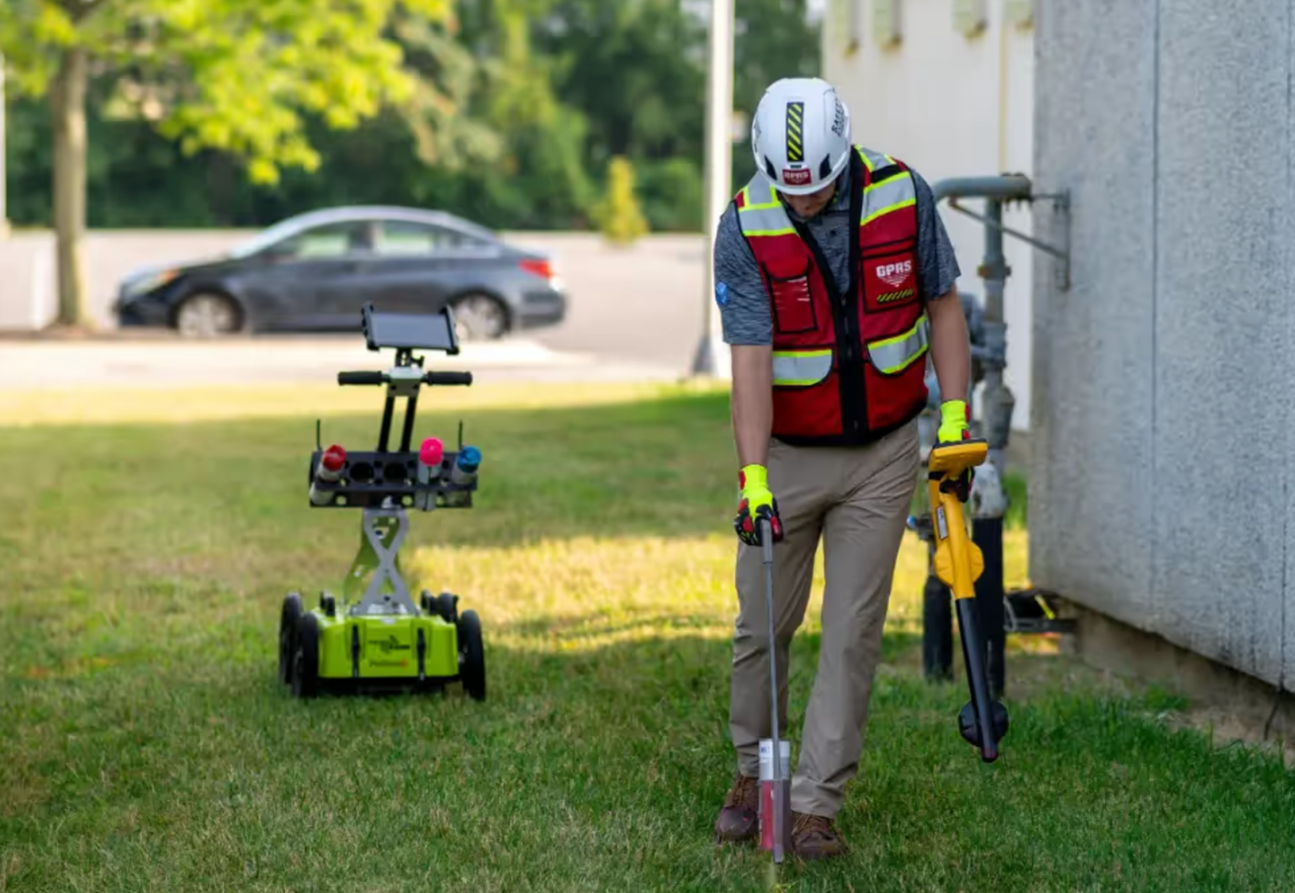
Phase 2: Field Investigation
Field investigation is the core of any geotechnical program. Teams drill boreholes at strategic locations across the site, typically using rotary or hollow-stem auger equipment, to collect samples and run in-situ tests at intervals throughout the soil profile. The Standard Penetration Test (SPT) (ASTM D1586), in which a split-spoon sampler is driven into the soil by a standard hammer dropped from a fixed height, is one of the most widely used field tests in the world, providing both a sample and an indirect measure of soil resistance.
The Cone Penetration Test (CPT) pushes an instrumented probe into the ground at a constant rate, continuously measuring tip resistance and sleeve friction to produce a detailed, real-time profile of soil stratigraphy. Other field techniques include vane shear testing for soft clays, pressure meter testing for in-situ stiffness, and geophysical methods such as seismic refraction and electrical resistivity surveys for broader subsurface imaging.
At GPRS, we utilize a thorough model called SIM or Subsurface Investigation Methodology. SIM is a standard operating procedure comprised of two specifications created for subsurface investigations, one for underground utility locating and one for concrete scanning. SIM is designed to achieve the most accurate results when performing non-destructive subsurface testing.
Phase 3: Laboratory Testing
Samples collected during field work are transported to a geotechnical laboratory for detailed testing. Index tests, including grain size analysis, Atterberg limits, and moisture content determination, classify the soil and provide a framework for predicting its engineering behavior.
More sophisticated strength tests, such as triaxial compression and direct shear, measure the parameters used in foundation and slope stability calculations. Consolidation tests define the rate and magnitude of settlement under sustained load. The combination of field and laboratory data gives engineers a comprehensive picture of subsurface conditions and the parameters needed for design.
Phase 4: Analysis, Design, and Construction Support
With a well-characterized subsurface model in hand, engineers run bearing capacity calculations, settlement predictions, and slope stability analyses using both hand methods and finite element or finite difference computer models. The results inform specific design recommendations: foundation type and depth, allowable bearing pressures, estimated total and differential settlement, required ground improvement, and excavation support requirements.
Many geotechnical engineers remain involved during construction to observe conditions exposed in excavations, verify that assumed bearing strata have been reached, and respond to unexpected conditions as they arise.
Where Geotechnical Engineering Shows Up
Geotechnical engineering is woven into the fabric of nearly every infrastructure sector. Its principles apply wherever a structure must interact with the ground – which is to say, everywhere.
- Buildings and Skyscrapers: High-rise buildings impose enormous, concentrated loads on small footprint areas, requiring deep foundation systems that can transfer hundreds of thousands of tons of load to competent bearing strata far below the surface. The geotechnical investigation for a major urban tower may involve dozens of deep boreholes, extensive laboratory testing programs, and three-dimensional computer modeling of foundation-soil interaction.
- Transportation Infrastructure: Roads, railways, bridges, and airport runways all depend on stable subgrade conditions. Differential settlement beneath pavement structures causes cracking, rutting, and safety hazards. Bridge foundations must be designed to resist not only vertical loads but lateral forces from wind, traffic, and scour – the erosion of streambed material around foundation elements during flood events.
- Dams and Levees: No application demands more rigorous geotechnical analysis than dam engineering. A dam failure releases catastrophic energy and can devastate communities for miles downstream. Geotechnical engineers evaluate seepage through and beneath the dam body, the stability of the embankment against sliding, and the risk of internal erosion – a gradual process in which seeping water progressively removes fine soil particles and eventually creates a continuous channel through the dam.
- Tunnels and Underground Structures: Tunneling requires detailed knowledge of rock and soil conditions along the entire alignment, often over distances of miles. Engineers must predict the stand-up time of the excavated opening, or how long the ground will remain stable without support, and design primary and permanent lining systems accordingly. Unexpected groundwater inflows and zones of weak or swelling rock are among the most common causes of tunneling delays and cost overruns. Unexpected tunnels can also delay or halt projects if they aren’t found before construction starts.
- Energy Infrastructure: Wind turbines, offshore oil platforms, and buried pipelines all present unique geotechnical challenges. Offshore platforms must resist wave and current loads through pile foundations driven into seabed sediments. Wind turbine foundations must handle cyclic lateral loading from rotating blades. Buried pipelines must be protected against soil movement from settlement, frost heave, and landslide activity. Experience is a must when it comes to navigating complex energy projects.
- Environmental Remediation: Landfill design and contaminated site cleanup require geotechnical expertise to characterize subsurface conditions, design containment systems, and ensure that engineered barriers prevent the migration of contaminants into groundwater and surrounding soil.
Common Challenges and Uncertainties
Geotechnical engineering is, at its core, a discipline defined by uncertainty. Unlike structural engineers who design with materials of precisely known properties, geotechnical engineers work with natural materials whose characteristics can shift dramatically over short distances.
A borehole provides an accurate picture of conditions at one point; extrapolating those conditions to the spaces between boreholes requires professional judgment informed by experience and geological understanding.
Groundwater levels fluctuate seasonally and in response to precipitation, irrigation, and neighboring construction activity. Construction operations like vibration from heavy equipment, dewatering of excavations, changes in drainage patterns, can alter subsurface conditions in ways that were not anticipated during the investigation phase. Unanticipated layers of weak soil, buried debris, or artesian groundwater conditions are encountered regularly on construction projects of any scale. Managing these uncertainties through conservative design assumptions, robust monitoring programs, and flexible construction protocols is a defining feature of competent geotechnical practice.
Seismic hazard adds another layer of complexity.
In earthquake-prone regions, geotechnical engineers must evaluate the potential for soil liquefaction. This is a phenomenon in which saturated, loose granular soils temporarily lose their shear strength in response to earthquake shaking and behave like a viscous fluid.
Liquefaction was responsible for widespread damage in the 1964 Niigata earthquake in Japan and the 1989 Loma Prieta earthquake in California, among many others. Modern codes require liquefaction assessments for projects in seismic zones and mandate mitigation measures when the risk is deemed unacceptable.
Ground Improvement Methods
When natural soil conditions are inadequate to support a planned structure without excessive settlement or stability risk, geotechnical engineers have a broad toolkit of ground improvement techniques to improve subsurface conditions prior to or during construction.
- Compaction and Densification: Mechanical compaction using rollers, vibratory plates, or tampers increases soil density and reduces void ratio, improving both strength and stiffness. Vibro-compaction uses a vibrating probe to densify loose sands over depth ranges not accessible to surface compaction equipment.
- Soil Mixing and Stabilization: Cement, lime, fly ash, or other binders can be mixed into weak soils, either mechanically or through injection, to create a stiffer, stronger composite material. Deep soil mixing is commonly used to create improved zones beneath foundations and to construct containment barriers around contaminated sites.
- Preloading and Surcharging: Applying a temporary load to soft compressible soils before construction accelerates consolidation and reduces post-construction settlement. The process can be expedited by installing vertical drains that shorten the drainage path for pore water expelled from the consolidating clay.
- Grouting: Injection of cement grout, chemical grout, or expanding polyurethane foam into soil or rock voids can fill cavities, reduce permeability, and improve strength. Compaction grouting displaces and densifies surrounding soil as grout is injected under controlled pressure.
- Geosynthetics: Geotextile fabrics, geogrids, and geomembranes are manufactured materials used to reinforce soil, provide drainage separation, and contain contaminants. Geogrid reinforcement is widely used in mechanically stabilized earth (MSE) retaining walls and reinforced embankments over soft ground.
Tools and Technology in Modern Practice
Modern geotechnical engineering has been transformed by advances in computational power, remote sensing, and instrumentation. These technologies do not replace professional judgment, but they substantially expand the engineer’s ability to characterize subsurface conditions, analyze complex problems, and monitor performance through the life of a structure.
Finite element and finite difference software packages allow engineers to model complex, three-dimensional soil-structure interaction problems that would have been intractable by hand calculation. Programs such as PLAXIS and FLAC are industry standards for modeling embankment stability, tunnel excavation, and foundation behavior under combined loading conditions. These models incorporate mathematical descriptions of soil stress-strain behavior (constitutive laws) that have been calibrated against decades of laboratory and field data.
Remote sensing technologies, including LiDAR (Light Detection and Ranging) and satellite-based InSAR (Interferometric Synthetic Aperture Radar), allow engineers to map terrain with millimeter-scale precision and detect subtle ground surface movements, sometimes even before visible distress has occurred. InSAR has been used to identify slow-moving landslides, monitor subsidence over underground mines, and track the performance of dam embankments over time. GPRS supports remote sensing technologies with highly trained teams who can scan and report all kinds of terrain.
Geotechnical instruments including piezometers, inclinometers, settlement plates, extensometers, and strain gauges allow real-time monitoring of groundwater pressure, lateral movement, and vertical deformation within and beneath active structures. When paired with automated data acquisition systems and threshold-based alert protocols, these sensor networks provide an early warning capability that can prevent failures or prompt timely intervention before conditions become critical.
Learning From Failures
Geotechnical engineering, perhaps more than any other branch of the discipline, has been shaped by its failures. The collapse of structures, the failure of slopes, and the catastrophic breach of dams have each revealed gaps in understanding and prompted the development of better investigation methods, more conservative design standards, and improved construction practices.
The 1928 failure of the St. Francis Dam in California, which killed an estimated 431 people, was caused by the failure of weak conglomerate rock and hydraulic uplift at the foundation contact. The 1976 failure of the Teton Dam in Idaho resulted from internal erosion through inadequately designed zones in the embankment.
The 2017 Oroville Dam spillway crisis, the most expensive dam failure-related incident in U.S. history, exposed the consequences of inadequate foundation investigation and material characterization in spillway design.
In each case, post-failure investigations led to lasting improvements in industry practice. The engineering profession treats these events not as embarrassments to be minimized but as essential sources of knowledge.
Detailed forensic analyses are published, peer-reviewed, and incorporated into design codes, training curricula, and professional guidelines so that the same failure mode does not recur.
Sustainability and Climate Resilience
Geotechnical engineers are increasingly called upon to address challenges at the intersection of infrastructure design and environmental change. Rising sea levels, intensifying precipitation events, and shifting drought patterns are altering the ground conditions that existing and future structures must contend with. Coastal erosion, increased landslide frequency, and frost pattern changes are among the hazards that are expected to intensify in many regions over coming decades.
The profession is responding with greater emphasis on adaptive design. Movement in the profession is toward designing infrastructure that can accommodate a range of future conditions rather than being optimized for a single historical baseline.
Geotechnical engineers also contribute directly to sustainability goals by recommending the reuse of existing foundations when structures are renovated or replaced, reducing the material and energy required for new foundation construction. Ground improvement techniques that stabilize native soils in place can eliminate the need to import large quantities of structural fill, reducing truck traffic, emissions, and cost.
Where the Field Is Headed
Several trends are reshaping geotechnical practice in the near term. Machine learning and artificial intelligence are being applied to large geotechnical datasets in the form of CPT records, borehole logs, and laboratory test results to identify patterns and correlations that improve the reliability of subsurface characterization.
Research institutions and major engineering firms are developing models that can predict soil behavior from regional datasets, reducing the number of site-specific tests required in well-characterized geological settings.
Autonomous drilling and sensing systems are beginning to enter the field investigation market, offering the potential for continuous subsurface profiling at lower cost. Wireless, low-power sensor networks which are embedded in embankments, slopes, and retaining structures, enable more comprehensive long-term monitoring of infrastructure performance than was previously economically feasible.
Dense urban environments are creating new demands for creative underground engineering. As surface space becomes scarcer in major cities, geotechnical engineers are working on increasingly complex deep excavation projects, underground transit extensions, and basement construction adjacent to sensitive existing structures.
The ability to predict and manage ground movement during excavation – protecting neighboring buildings, utilities, and tunnels from damage – is among the most technically demanding aspects of contemporary geotechnical practice.
The Bottom Line
Geotechnical engineering rarely appears in project announcements or ribbon-cutting ceremonies. It operates below the surface, literally and figuratively, and its most important contributions are the disasters that never happen.
The evidence for proper geotechnical engineering is in the foundations that never settle, the slopes that never fail, and the dams that never breach. Yet every single structure on earth that stands safely above grade does so because someone first determined that the ground beneath it was capable of bearing the load or took the necessary steps to make it so.
As construction grows more ambitious and climate conditions grow more variable, the discipline’s role will only continue expand. The ground is always there, and understanding it rigorously, scientifically, and with appropriate humility about what remains unknown, is among the most consequential things an engineer can do.
Frequently Asked Questions: What Is Geotechnical Engineering?
What do geotechnical engineers actually do?
Geotechnical engineers investigate the soil, rock, and groundwater conditions beneath a site to determine whether the ground can support a planned structure. They collect field samples, run laboratory tests, and produce design recommendations for foundations, slopes, retaining systems, and ground improvement. On active construction projects, they also observe exposed conditions in excavations and respond when the ground behaves differently than anticipated.
Why does geotechnical investigation matter before construction begins?
Subsurface conditions vary significantly, even across small distances. A site may conceal soft clay layers, buried organic material, abandoned utility corridors, or voids that are invisible from the surface. When those conditions go undetected, structures can settle unevenly, slopes can fail, and foundations can lose bearing capacity. Early geotechnical investigation identifies these risks before construction begins, reducing the probability of costly failures and construction defect litigation.
What happens during a geotechnical investigation?
A complete investigation moves through four phases. The desk study compiles existing geological maps, nearby borehole records, historical photographs, and prior land use data. Field investigation follows, with crews drilling boreholes and running in-situ tests such as the Standard Penetration Test (SPT) and Cone Penetration Test (CPT) to measure soil resistance throughout the profile. Collected samples then go to a geotechnical laboratory for index testing, shear strength testing, and consolidation analysis. Finally, engineers synthesize all data into bearing capacity calculations, settlement predictions, and specific foundation or ground improvement recommendations.
GPRS supports subsurface investigation teams by locating and marking utilities before drilling begins. Utility locating prior to soil boring protects field crews and prevents line strikes that delay investigations.
What is Subsurface Investigation Methodology (SIM), and how does GPRS use it?
SIM, or Subsurface Investigation Methodology, is a standard operating procedure GPRS developed for non-destructive subsurface testing. It comprises two specifications: one for underground utility locating and one for concrete scanning. SIM follows a three-step approach focused on achieving the most accurate results before any intrusive work begins. By applying SIM on geotechnical projects, GPRS helps investigation teams work with confidence, protecting the borehole program from damage or unexpected line strikes.
What are soil borings, and why are they central to geotechnical investigations?
Soil borings are drilled holes advanced into the ground to collect soil and rock samples at depth. They are the primary method geotechnical engineers use to directly observe and test subsurface conditions. During a boring program, crews drill at strategic locations across a site and extract samples at regular intervals using split-spoon samplers, thin-walled tube samplers, or core barrels, depending on soil type and required sample quality. Those samples are logged in the field and sent to a laboratory for index testing, strength testing, and consolidation analysis.
Soil borings also allow in-situ testing. The Standard Penetration Test (SPT), one of the most widely used field tests in the world, measures soil resistance by counting the blows required to drive a sampler a set distance, providing both a physical sample and an indirect measure of density and strength. Before any boring program begins, locating and marking buried utilities is a required step. GPRS locates underground utilities prior to soil boring to protect field crews and prevent costly line strikes that halt investigations.
What types of infrastructure require geotechnical engineering?
Geotechnical analysis is required wherever a structure interacts with the ground, which covers nearly every infrastructure category. High-rise buildings require deep foundation systems to transfer enormous, concentrated loads to competent bearing strata. Roads, railways, and bridges depend on stable subgrade conditions. Dams demand rigorous analysis of seepage, embankment stability, and internal erosion risk. Tunnels require detailed knowledge of rock and soil conditions along their entire alignment. Energy infrastructure such as wind turbines, offshore platforms, and pipelines each present unique geotechnical loading and movement challenges.
How do geotechnical engineers manage groundwater on construction projects?
Groundwater reduces the contact stress between soil particles, which decreases shear strength and can push a stable soil profile toward failure. Engineers design subdrainage systems, impermeable cutoff walls, relief wells, and temporary dewatering systems to control groundwater during both construction and long-term operations. GPRS supports water and sewer infrastructure teams by locating existing buried utilities before excavation or dewatering work begins, reducing the risk of conflicts with underground systems.
What role do modern technologies play in geotechnical practice?
Finite element software such as PLAXIS and FLAC allows engineers to model complex three-dimensional soil-structure interaction that manual calculations cannot resolve. LiDAR and satellite-based InSAR detect millimeter-scale surface movements and can identify slow-moving landslides or subsidence before visible distress appears. Piezometers, inclinometers, and automated sensor networks provide real-time monitoring of groundwater pressure and lateral movement in embankments, slopes, and retaining structures throughout the operational life of infrastructure. Machine learning is also entering the field, being applied to large datasets of borehole logs and CPT records to improve subsurface characterization accuracy.
GPRS supports geotechnical and remote sensing programs with trained field teams capable of scanning, locating, and documenting subsurface conditions across a wide range of terrain and project types.
How does geotechnical engineering connect to environmental work?
Geotechnical expertise is central to environmental due diligence, remediation planning, and landfill design. Engineers characterize subsurface conditions at contaminated sites, design containment systems to prevent contaminant migration into groundwater, and evaluate existing fill materials that may have been placed without engineering controls. GPR supports environmental and geotechnical teams by providing non-destructive subsurface imaging before intrusive work begins, which protects field crews and reduces the risk of disturbing buried hazards.
How does GPRS support geotechnical investigations?
GPRS provides a suite of services that directly supports geotechnical and environmental field programs. Ground-penetrating radar (GPR) locates and maps buried utilities, tanks, and anomalies before soil borings or excavations begin, preventing line strikes and protecting field crews. SiteMap®, GPRS’s infrastructure mapping platform, allows project teams to document and share subsurface findings in a single accessible location. For complex or remote sites, GPRS teams apply reality capture services to produce accurate as-built records of existing conditions that support design and construction decision-making.
Contact GPRS to discuss how our subsurface investigation services can support your next geotechnical program.
Five Solutions to Stabilize Brick & Mortar Retail Locations in an Omnichannel Marketplace
Trends that began in response to pandemic lockdowns created some new shopping behaviors, but mounting evidence suggests that American consumers are hungry for a return to third spaces and in-person interactions, especially in retail.

According to The Harvard Business Review, “The past seven years have arguably been the most tumultuous in recent retail history: Covid, major technology changes, tariffs, and higher interest rates have reshaped buying and selling in the sector. But the tumult has also clarified realities.” Among those realities are the lowest shopping center vacancy rate since 2004 – just 5.4% – and the rise of the Gen Z brick and mortar shopper.
Those data points, when added to the U.S. Census Bureau data cited below, may signal a shift in American shopping habits.
"[S]tore replacement by e-commerce and direct-to-consumer (DTC) models – has stalled… e-commerce as a portion of U.S. retail sales in 2025 were 16.4%, barely above the 16.3% it reached during the second quarter of 2020 (maximum lockdown conditions during the pandemic), and its annual increases in each of the past four years have been their lowest since the Great Recession of 2008-2009.”
What does this all mean? It could mean adapting physical retail locations to survive and thrive in our e-commerce world may be less of a challenge for vendors across the U.S. than previously thought.
It seems we’re approaching a reset in retail in favor of brick and mortar, in-person shopping experiences, which could be lucrative for commercial real estate owners, management companies, and, of course, retailers themselves.
With an apparent trend toward physical spaces, the fundamentals of assessing, planning, executing, and optimizing retail space remain constant. Whether you’re a seasoned retail or QSR pro, or a new entrepreneur looking to make a mark, what follows are the foundational elements to keep in mind as you prepare for the world of omnichannel retail.
Due Diligence for Multi-Generational and Second Gen Retail Spaces
Second generation spaces can be a big win for retailers because they may already have plumbing, HVAC, restrooms, kitchens, or other costly systems in place, which can lower buildout time and help a tenant open faster. However, the very benefits that make adapting a second-gen space attractive can also hide problems. Older systems may need updating or repair, existing layouts may not fit brand guidelines, and past use cases may have created code, health, or environmental issues. So, it’s vital to have accurate existing conditions documentation on every part of the structure, aboveground and below, before planning the fit-out.
The affordable multi-gen space can pile on costs once repairs, permits, and upgrades are counted. That’s why it pays to fully assess any second-gen space’s structure, MEP/HVAC, amenities, tooling, utilities and tie-ins with as much care as you assess foot traffic patterns and speed to market.
A strong due diligence plan should check structure, roof, floor loads, grease traps and clean-outs, electrical service, plumbing, HVAC, ADA access, fire safety, egress, zoning, signage rights, and parking. Adaptive reuse guidance stresses that teams should assess what already exists, decide what must change, and what barriers could stop the intended use. Retail spaces that serve the public must also plan for accessible parking and routes, since ADA rules apply to businesses open to customers. The goal is simple: know the risks before signing the lease, buying the asset, or setting an opening date.
Curbside Pickups, Signage, and Drive-Thru Expansions
Curbside pick-up lanes, signage, and drive-thru design are now core retail tools, not extra features, and not just limited to restaurants. Major retailers from grocers to specialty stores now incorporate order pick-up lanes in their operations.
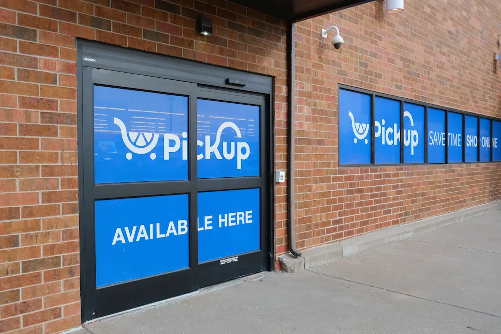
Post-pandemic, according to The National Restaurant Association, nearly 75% of restaurant traffic is off-premises, with many limited-service operators reporting that off-premises sales are significantly larger than in 2019. Customers also care about speed, service, and value, so a confusing pickup or drive-thru lane can hurt sales fast. For QSRs, this can mean lost cars in line. For retailers, it can mean missed pickups, unsafe parking lots, and poor reviews.
Traffic flow, pedestrian safety, employee walking paths, ADA spaces, order handoff zones, queue length, menu boards, lighting, and weather protection are just some of the items that must be taken into account when designing curbside and drive-thru spaces. Curbside programs may also affect leases because dedicated parking, common areas, site plans, insurance, and signage often need landlord approval. Accessible parking must stay on the shortest accessible route to the entrance, with proper signs, slopes, access aisles, and van-accessible spaces where required. Good signage should tell drivers where to go before they feel lost.

The best plans keep cars moving, protect people on foot, and make pickup feel simple to lock-in repeat business.
Tenant Improvement & Adaptive Reuse
Adaptive reuse and tenant improvement (TI) are both vital because they turn a leased box into a working store, restaurant, or service space. For retail tenants, TI often covers items like flooring, lighting, walls, HVAC, plumbing, storefront work, and other lasting improvements. For QSRs, buildouts can be more complex because kitchens, hoods, grease systems, drive-thru equipment, and power loads can raise costs. TI allowances are also a major lease negotiation point because they affect rent, cash needs, and the final deal.
Adaptive reuse has gained significant traction post-2022, as retail and office tenancy rates weakened, allowing enterprising architects and developers a chance to reimagine spaces. This trend has led to a solid increase in mixed-use properties in urban areas that marry residential with retail and restaurant tenancies. Reimagining these spaces does, however, require careful planning to execute within budget constraints.

New Construction Retail Rollouts
New construction gives CRE firms, solo retailers, and QSRs the most control. It allows you to plan the building, site flow, drive-thru, parking, signage, utilities, kitchen, pick-up areas, and customer path from the start. Including due diligence in a new construction real estate strategy can shape an organization’s revenue, operations, and brand value for years. It also helps retailers build a consistent customer experience across many markets.
The downside, of course, is that new builds can take longer and cost more than second-gen spaces. So, planning must be tight, which further reinforces the need to have all existing conditions information in hand before making decisions. Confirmation of zoning, entitlements, utility locations and capacity, stormwater needs, access points, traffic counts, delivery routes, ADA parking, fire access, and local sign rules are just a few of the hundreds of project points that must be considered. For instance, according to The U.S. Access Board, ADA guidance says new parking facilities must include accessible spaces, access aisles, proper slopes, signs, and van-accessible spaces based on the lot size. In the QSR world, off-premises demand means the site should support takeout, delivery, curbside, and drive-thru without creating unsafe conflicts. A good rollout plan uses repeatable standards, yet remains adaptable for each store to the local parcel, customer base, and approval processes.
Multi-Site Solutions
For businesses with multiple locations, a multi-site portfolio plan ensures every location/franchise operates the same way while tailoring themselves to local market interests/concerns. Customers have come to expect consistent brand recognition, easy access, and smooth service at every location. QSR real estate choices, in particular, can impact sales, speed, labor costs, and long-term brand value. So, site selection and planning must be disciplined, not rushed.

When planning or updating across a retail portfolio, repeatable standards make layout, signage, back-of-house areas, ADA access, pickup zones, and brand finishes easier. However, each site still needs its own due diligence. A small urban store, a suburban drive-thru, and a second-gen renovation may need different service paths, buildout costs, and utilities. Off-premises dining is now a major part of restaurant traffic, so QSR and retail sites must also support takeout, curbside, and delivery without hurting walk-in customers.
CRE (commercial real estate) teams must consider traffic patterns, visibility, parking, utilities, zoning, delivery access, and a nearby customer base before choosing sites. CBRE, the most prominent CRE management firm and consultancy, notes that strong retail outcomes depend on data, market insight, and expert review across many property types.
GPRS offers a unique solution for multi-site portfolio retail management in SiteMap®, our proprietary cloud-based platform that can house all your GPRS-collected data, and field to finish solutions like utility maps, NASSCO MACP, LACP, and PACP reports, CAD/BIM deliverables, and more.
Retail Market Outlook – A “Critical Moment” or a Brick & Mortar Opportunity?
Tariffs, AI, and a surge in acquisitions are just a few of the market trends retailers have to factor into their planning in the coming years. But it’s not all bad news, especially for brands willing to differentiate themselves with exceptional value and/or services, and the marked rise in both mixed-use projects and B malls, signaling a potential surge in brick-and-mortar retailing.
For instance, both Amazon and Costco saw double-digit retail increases in November of 2025, according to Navy Federal Credit Union as reported in Retail Dive, and Fitch expects that market share gains will favor “retailers with a strong set of assets, including robust supply chain infrastructure, a well-maintained store network and e-commerce platforms, healthy cash flow generation to invest in new capabilities, and clear differentiation that inspires customer loyalty.”
According to Price Waterhouse Cooper, we are at a “critical moment for business leaders to reevaluate their portfolios, doubling down on category strengths, accelerating innovation, and potentially exiting lines where competitive edge has faded.”
PwC cites trends regarding private equity’s caution in taking on new investment, and the fact that international buyers think a distressed retail market could smooth their paths to the U.S. consumer.
Service providers like AlixPartners agree, believing that the watchwords for 2026 and beyond are uncertainty and disruption in what they call the “broadly static” retail landscape. They cite the potential “eureka moment” of AI, the push/pull of e-commerce v. brick and mortar stores, the economic impacts of world events, and the critical importance of capital conditions on ROI and its potential effects on IPCo and OpCo models (Intellectual Property Company and Operating Company) for Mergers and Acquisitions.
All of this is in line with PitchBook’s prediction of a “K-shaped economy,” where the haves continue to outpace the have-nots. Forrester specifically expects a wave of bankruptcies among specialty retailers and those with high debt loads as they hit a “breaking point,” and urges stable household brand retailers to optimize their brick-and-mortar stores for unique customer experiences while aggressively pursuing omnichannel retailing, and debt reduction. One of the specific predictions Forrester’s Principal Analyst Sucharita Kodali makes is that “generous” return policies for online retailers will end abruptly, as AI tracks customer behavior, and all retailers strive to hang onto profit margins.
Whether you’re developing your first retail space, operating a chain, or managing a nationwide portfolio, GPRS Visualizes The Built World® to give you the accurate existing conditions information you need and makes it secure, shareable, and accessible for your teams.
What can we help you visualize?
Frequently Asked Questions
How, specifically, can GPRS help retail developers?
Our elite team of Project Managers are Subsurface Investigation Methodology (SIM) certified, which means each PM receives a minimum of 80 hours of classroom training and 320 hours of mentored field training in utility locating & mapping, concrete scanning, video pipe inspections for sanitary and storm sewer lines, pinpoint leak detection, and 2-4mm accurate reality capture. Our PMs can choose to specialize in one of the above disciplines, but they are all trained in every part of existing conditions data capture to provide the most accurate measurements and information available.
GPRS has maintained a less than 0.20% at-fault incident rate on well over one million utility locating and concrete scanning jobs, and we are the only national company that guarantees our concrete scanning work with the Green Box Guarantee.
You can learn more about how our suite of services can meet your specific retail needs by visiting our retail industry page for more information.
Can you explain how SiteMap® helps manage retail and QSR portfolios?
SiteMap is GPRS’ proprietary cloud-based GIS and data management platform. It is the delivery mechanism for all of your GPRS findings, including NASSCO WinCan video pipe inspection reports, RTK-located, interactive utility maps, CAD/BIM deliverables, walkthrough tours, 3D photogrammetry, and more. Every GPRS customer receives complementary SiteMap Personal access to view, print, share, and utilize their GPRS-captured site data 24/7 from anywhere. Additional access levels, including Project, Project 360, Pro, and Team, provide greater collaborative access and administrative permissions that put you in control of your site information from field to finish.
You can schedule a free demo of SiteMap, here.
How accurate are GPRS’ findings?
GPRS has maintained an at-fault incident rate of less than 0.2% over more than one million utility locating and concrete scanning jobs since 2017. We say we are in pursuit of 100% subsurface damage prevention, and our numbers prove our commitment to that mission.
That same accuracy is reflected in our PACP-coded video pipe inspection reporting, which includes pipe location, flow direction, depths, and pipe materials where available, and precisely captures and catalogues all pipe conditions, defects, and severity to NASSCO standards.
In reality capture, we utilize 3D LiDAR scanners and photogrammetry to achieve 2-4mm accurate raw measurements, with an average of 2-6mm accuracy in our CAD/BIM deliverables.
How to Mitigate Risk During Compound Expansions
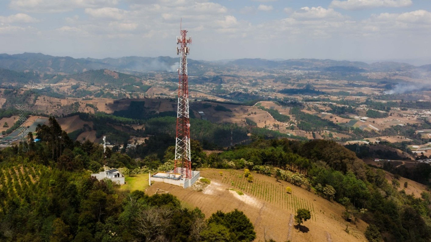
The speed and coverage needed for you to do things like read this article require a lot of complex infrastructure nationwide. Telecom providers are scrambling to upgrade their equipment and technology, even when their physical space is limited.
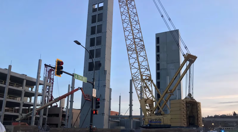
The industry term for this continual push for more is compound expansion. Compound expansions occur when adding physical space and/or equipment to an existing telecommunications site, also known as a tower compound, to broaden coverage, allow for technology upgrades, or accommodate additional telecom tenants.
The compound expansion process typically involves:
- Site assessments by field engineers
- Lease negotiations
- Obtaining building permits and zoning approvals from local municipalities
- Excavation and foundation work
- Erecting a new perimeter fence
- Connecting the upgraded infrastructure into the existing cables
- Integrating and testing the new equipment
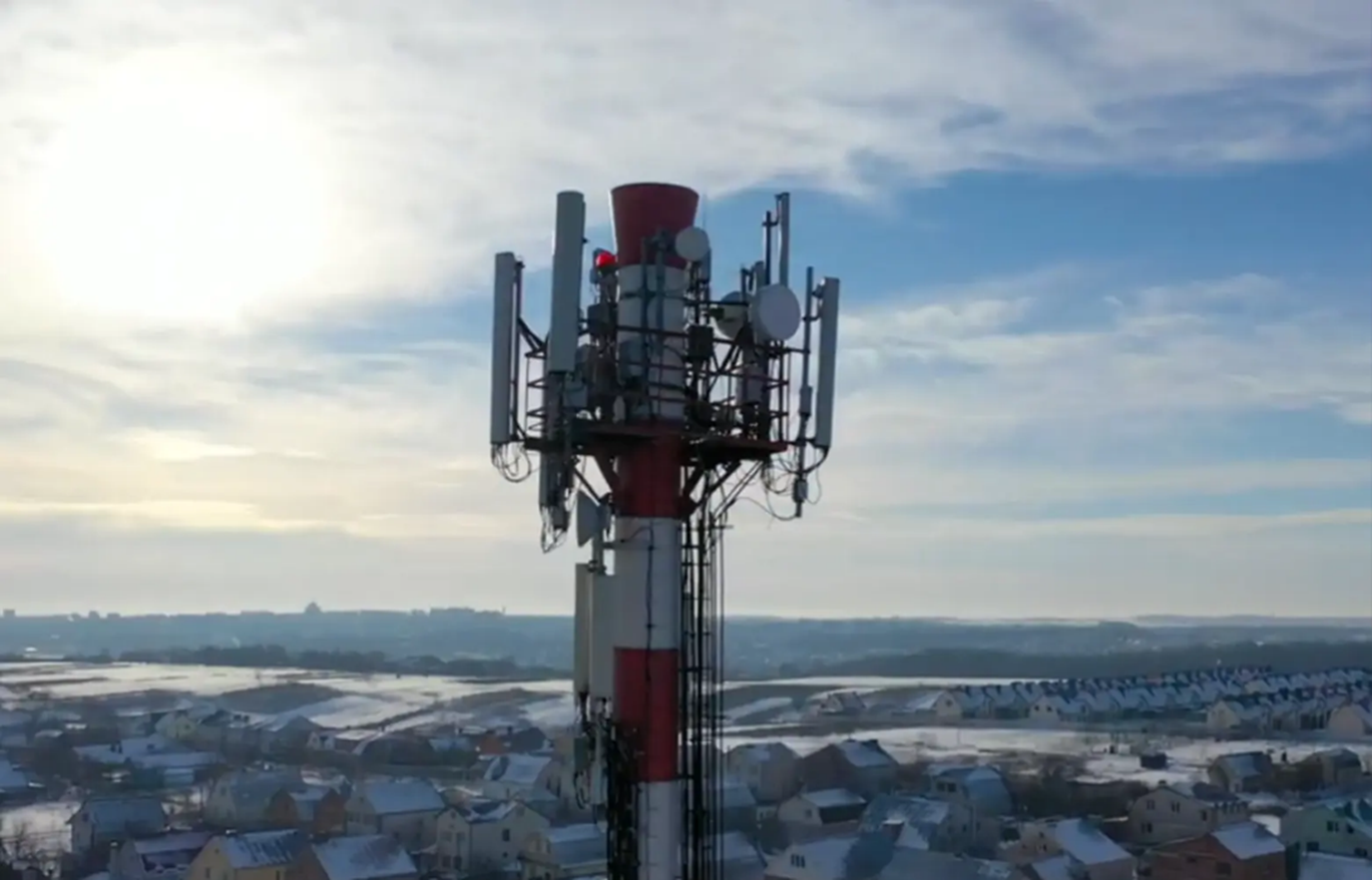
The densification of 5G network towers across the United States plays a huge role in the need for compound expansions. As more providers strive toward superior network reliability, that means more wireless towers need specific infrastructure that they don’t have the space for and they need them quickly.
Because these expansions are moving at breakneck speeds, federal policies have been put in place to make the process smoother. In October of 2020, the Federal Communications Commission (FCC) voted on policies to accelerate the process of existing compound expansions as long as it does not “substantially change the physical dimensions of the structures.” The ruling also stated that the new equipment and infrastructure cannot increase the area by more than 30 feet.
So, even though there are initiatives in place to assist with the densification of 5G, there are still limits.
Examples of the kinds of technology upgrades that would warrant a compound expansion include additional cabinets to house sensitive hardware, like routers and cables, upgraded HVAC systems, high-capacity backup generators, and solar panel integrations.
Tight deadlines and rising demand create risk when performing these upgrades. Some of the risks your team can encounter when performing compound expansions include:
- Striking existing utilities or concrete reinforcements during excavations
- Electrical and fire hazards
- Structural failure during installation
- Legal action from lease and zoning noncompliance
Applications and services that mitigate these risks must be utilized to ensure projects stay safe and on schedule.
How to Mitigate Risk on Compound Expansion Projects
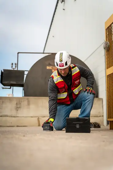
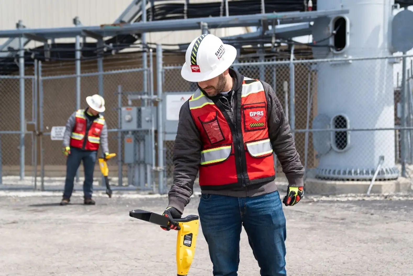
Utility and Concrete Scanning
Whether you are breaking ground to install a fence or a new back-up power generator, it’s vital to know what’s underground first. A line strike at a wireless tower compound can result in service outages, high repair costs, and fatal injuries for workers.
It’s vital to call your local 811 before performing any digging on site. However, since not all utility owners are registered with 811, you should also hire a professional utility locating company like GPRS to provide you with complete utility locating information before you put a shovel or bucket in the ground.
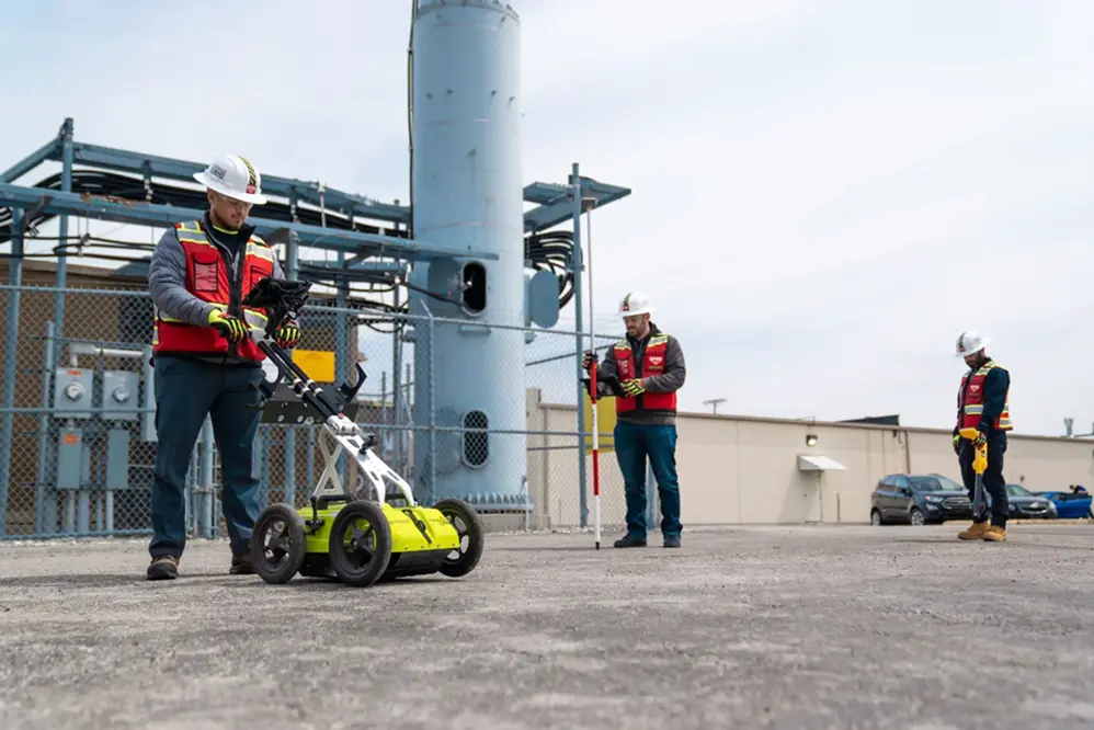
Striking concrete reinforcements, like conduit and post tension cables, is just as dangerous to a project as a utility strike when cutting or coring into concrete slabs. Concrete scanning professionals, like GPRS Project Managers, provide you with a full view of where it is and isn’t safe to cut or core.
A complete map of what lies beneath your feet will keep your team safe and the project on time.
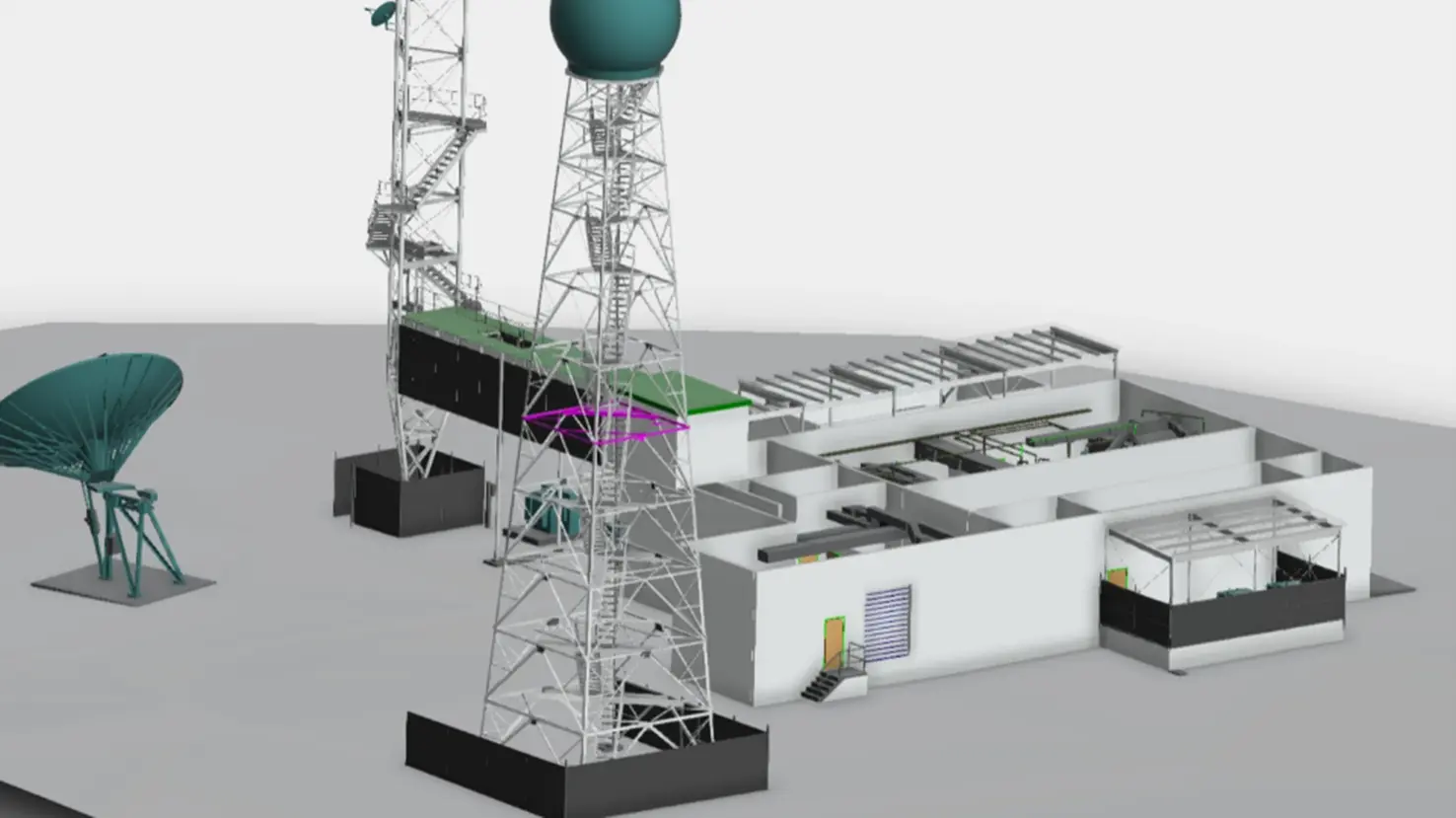
Updated Existing Conditions Documentation and As-Builts
During the design process, precise and up-to-date measurements are crucial to make sure everything is properly mapped out and scheduled. Paper plans are hard to rely on and manual hand measuring tactics are not practical anymore in this fast-moving industry. Without documentation a team can trust, they are more susceptible to electrical hazards, structural failures, and legal noncompliance.
When developing existing conditions documentation, the level of accuracy obtained using LiDAR-based 3D laser scanners is second to none. If it is operated by a professional, like GPRS Reality Capture Project Managers, the data produces a point cloud file that is 2-4 mm accurate.
And once that data is gathered, professional CAD technicians use that data to develop 2D drawings and 3D models that are also millimeter accurate.
Deliverables that could assist your next compound expansions include:
- 2D CAD Drawings
- 3D BIM Models
- 3D Revit Models
- 3D Mesh Models
- BOMA Calculations
- Virtual Walkthroughs
- At-Depth Modeling
With precise drawings and models of your site at your disposal, your team can:
- Avoid electrical and fire hazards through the development of MEP as-builts and 3D BIM models to generate clash detection reports
- Reduce the risk of structural failure by providing engineers with highly accurate structural as-builts for enhanced planning capabilities
- Lower the risk of legal noncompliance with a detailed layout of the property that helps make sure planned renovations don’t exceed zoning and leasing restraints
GPRS + SiteMap® = Your Single Source of Truth
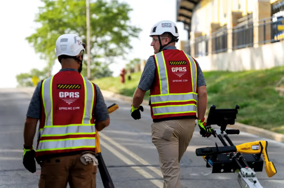
With hundreds of SIM-certified Project Managers in the field across the country, GPRS can provide compound expansion projects with the solutions they need within their tight deadlines. From the design phase to post construction analysis, GPRS’ field-verified data can help.
Each service offered by GPRS provides site owners, general contractors, and engineers with very useful information when planning and executing compound expansions.
GPRS Project Managers have maintained a less than 0.20% at-fault incident rate in concrete scanning and utility locating since 2017, so your team can dig with confidence with GPRS on your team.
And our Reality Capture Project Managers and in-house Mapping & Modeling Team can bring every millimeter of your site into clear view to allow for better planning and execution of the project.
All this data and more is securely housed in our cloud-based infrastructure management platform, SiteMap (patent pending).
SiteMap started as a utility data platform where our Project Managers use GPS and RTK-positioning to digitally document their findings and upload them into the platform. The platform has evolved to add state-of-the-art features to its utility data storage capabilities, including:
- The Reality Capture Layer that stores all your site’s point clouds, virtual walkthroughs, and Revit models in digital areas that are geospatially accurate
- The Sewer Layer that keeps all your NASSCO-certified VPI reports, CCTV footage, and anything else you would need to know about your sewer lines in one task bar
- SiteMap Mobile’s Augmented Reality Feature that gives you the ability to see your site’s underground utilities above ground through your phone or tablet camera
- History Slider that allows you to see how your site has changed throughout the course of your projects
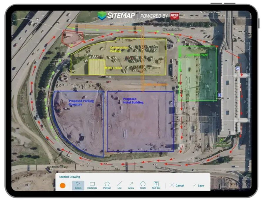
Another SiteMap feature that would be very useful while performing compound expansions is My Dig Board. With so many things happening so quickly on site, critical information can get lost in the job trailer.
My Dig Board acts as your digital job trailer that you can use to instantly update so your team to keep them in the loop in real time. If you change a material delivery area, or where you will be pouring fresh concrete, you can map it out right in the platform with shapes, arrows, and text boxes, so no information gets lost in the chaos. And as long as the appropriate people have access, whether it’s a team of contractors and trades, or multiple telecom tenants, everyone stays updated.
With all your site’s data in the palm of your hand 24/7, compound expansion projects can progress safely and efficiently so the initiative can finally catch up to the demand.
From concrete to cabinets, GPRS Visualizes YOUR Built World® above and below-ground to ensure your projects in the telecom industry stay on time, on budget, and safe.
What can we help you visualize?
FREQUENTLY ASKED QUESTIONS
What is SIM?
Subsurface Investigation Methodology (SIM) is a standard operating procedure and set of professional specifications that work as a guide for utility locating experts when scanning for buried utility lines. All GPRS Project Managers are required to achieve SIM 101 certification, which requires 80 hours of hands-on training in a classroom setting and 320 hours of mentorship in the field. For reference, the American Society for Nondestructive Testing’s (ASNT) minimum training recommendation includes eight hours for training and 60 hours practicing GPR to achieve NDT Level 1 certification in ground penetrating radar (GPR) scanning.
SIM requires the use of multiple, complementary technologies, like GPR scanning and electromagnetic (EM) locating, when locating buried utilities or scanning a concrete slab.
Can SiteMap scale as my portfolio grows?
Yes. SiteMap is designed to scale from a jobsite to a multi-site or campus-wide portfolio.
The platform centralizes utility maps, CADD/BIM files, drone imagery, and sewer records in one secure system that can be accessed across teams.
GPRS supports that growth by collecting above and below-ground site data, providing controlled sharing, and keeping information available 24/7 on desktop and mobile devices.
Request a demo of SiteMap here to learn more about the platform.
Can GPRS support fast rollouts?
Yes, GPRS can support fast project rollouts with nationwide coverage. We have a team of over 500 Project Managers in the field ready to meet your project’s needs in a timely manner.
Our team can provide yours with data and deliverables to keep your projects on time, on budget, and safe.
And as our team uploads site data into SiteMap, teams can reference that data in future projects and have data they can rely on at all times.
Request a quote for any of GPRS core services here.
How are utility maps delivered?
Along with being delivered as interactive GIS layers via SiteMap, GPRS utility maps are delivered as PDFs, CAD files, and KMZ exports.
Each format gives teams the ability to view, share, and integrate subsurface data into their workflows and ensure they avoid utility strikes. Your team can reference that data in future projects and have data they can rely on at all times.
How GPRS Helped Andersen Concrete Avoid Tearing Out a Brand-New Bridge Deck
Concrete is one of the most thoroughly understood materials in construction. Contractors and engineers have been refining mix ratios, curing times, compressive strength, and other variables for more than a century. But every so often, a problem surfaces that even experienced crews have never encountered before.
That was the situation facing Andersen Concrete after a topping slab was poured on a two-lane bridge in Grove City, Ohio. Crews began noticing cracking and surface imperfections developing in the freshly placed concrete. When they looked closer, the cause was something most people on site had never seen: fiber balls.
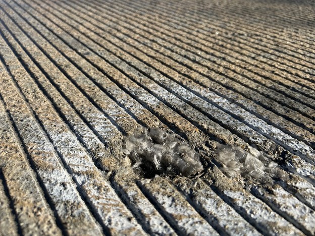
Synthetic reinforcement fibers are a common additive in modern concrete mixes. When properly blended, the fibers distribute evenly throughout the pour, improving tensile strength and reducing cracking. But in this case, the fibers failed to mix properly inside the truck. Instead of dispersing, they clumped together into dense masses that traveled with the pour and became embedded throughout the slab.
“They’re not supposed to clump up into balls,” explained GPRS Project Manager Derrik Clark. “They’re supposed to be all separated.”
Some of the defects had already begun pushing through the surface, visible as cracks and rough patches in the newly finished deck. But the ones already showing were not the real problem.
“The issue is the ones that have not come to the surface yet,” Clark said.

The fiber balls embedded below the surface would continue to migrate upward over time, driven by the natural expansion and contraction of curing concrete and seasonal temperature changes. Each one that broke through would bring cracking and surface damage with it. On a bridge deck, a compromised surface is an especially concerning structural liability because of the strategic role of bridges in the flow of transportation.
Andersen Concrete ran the numbers on their options. Demolishing and repouring the entire topping slab would have been, as Clark put it, “astronomical” in cost. They needed a way to find and remove only the compromised material while leaving sound concrete untouched.
The problem was that nobody could see where the remaining defects were hiding.
Clark had actually encountered this defect once before at a firehouse job just a few weeks earlier. He had scanned that slab and found clusters of anomalies in areas that also showed surface evidence of fiber ball activity. At the firehouse, however, no one cored to verify while he was on site, so he left without direct confirmation that what he’d found were actually fiber balls.
“I did that whole fire department job basically not being 100% sure that I was finding them, but thinking I was, just based on the areas where I was finding more anomalies,” Clark explained. “So that was kind of like a test run.”
On this bridge project, however, there was clear proof of the problem.
Clark used a concrete scanner equipped with ground penetrating radar (GPR) to work his way systematically across the bridge deck.
Unlike a utility locating job, where targets follow predictable linear paths, fiber balls can appear anywhere in the slab, without a pattern and no predictable orientation to follow. Some were isolated. Others appeared in clusters of two or three within a ten-foot section, then nothing for twenty feet, then several more in another concentrated area.
“There’s no rhyme or reason to it,” Clark said.
To account for that randomness, Clark worked in four-inch increments. He scanned a path, took a step, and scanned again, methodically covering the full deck to maximize the chance of detection. The scanner’s capture width is roughly four inches, so any gap in coverage could mean a missed defect.
“It was very strenuous scanning,” he said. “I tried to identify as much as I possibly could for them.”
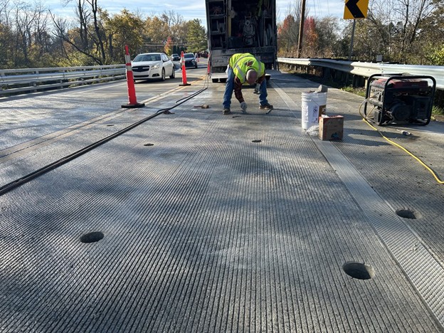
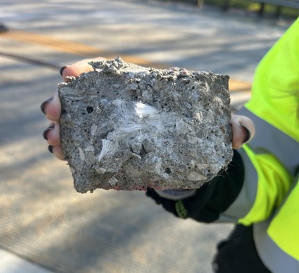
As Clark marked anomalous locations, Andersen Concrete crews followed directly behind him, coring into each flagged spot. Each time they pulled a core, they found a fiber ball. These clumps of synthetic fiber varied in size. The team was able to pull them out of the slab one by one and repair the bridge deck for good.
“When they started coring where I was locating anomalies and pulling out fiber balls, we knew the process worked,” Clark said.
The slab was three inches thick. Everything Clark was scanning for existed within that narrow window. Crews cored the defective sections, removed the compromised material, and patched the holes the same day, getting the bridge back open on schedule.
For Clark, it was a job unlike anything in the standard GPRS playbook. He had called the training department before the firehouse job, and they had doubts about whether GPR could even detect something like this.
“I don’t think they had actually ever heard of it,” he said. “Not saying that nobody’s ever done it, but it’s something that is probably fairly rare. And something that’s now proven that we can find. Kind of an opportunity where, if it ever does come up again, which it may not, it is something that we could be utilized for.”
From bridge decks to buried utilities, GPRS Visualizes the Built World™, above and below-ground.
What can we help you visualize?
FREQUENTLY ASKED QUESTIONS
WHAT ARE FIBER BALLS IN CONCRETE?
Fiber balls are dense clumps of synthetic reinforcement fibers that form when fibers fail to distribute evenly during the concrete mixing process. Instead of dispersing throughout the mix, the fibers tangle together into compact masses. When the concrete is poured, these clumps become embedded in the slab. Over time, they migrate toward the surface, causing cracking and compromising the structural integrity of the concrete. The defect is rare but can affect any pour that uses synthetic fiber reinforcement.
WHAT IS GROUND PENETRATING RADAR (GPR)?
Ground penetrating radar (GPR) is a non-destructive scanning technology that transmits electromagnetic pulses into a surface and measures the reflected signals to identify subsurface conditions. In concrete scanning applications, GPR can detect embedded objects, voids, delamination, and anomalous areas within a slab without cutting, coring, or damaging the structure. GPRS Project Managers use GPR to scan concrete slabs, bridge decks, walls, and other structural elements across a wide range of construction, infrastructure, and facilities applications.
Learn more about GPRS concrete scanning services here.
WHAT IS SIM?
Subsurface Investigation Methodology (SIM) is a standard operating procedure and set of professional specifications that guide utility locating experts when scanning for buried utility lines. All GPRS Project Managers are required to achieve SIM 101 certification, which requires 80 hours of hands-on classroom training and 320 hours of mentorship in the field. For reference, the American Society for Nondestructive Testing’s (ASNT) minimum training recommendation includes eight hours of training and 60 hours of practice to achieve NDT Level 1 certification in ground penetrating radar scanning. SIM requires the use of multiple complementary technologies, such as GPR scanning and electromagnetic (EM) locating, when locating buried utilities or scanning a concrete slab.
WHAT CONCRETE SCANNING SERVICES DOES GPRS PROVIDE?
GPRS provides a full range of concrete scanning services, including:
• Rebar and post-tension cable locating
• Conduit and utility locating within slabs
Why Aggressive Growth Demands More Than a Local Crew Strategy
The Rig That Got You Here Won’t Get You There
If you’re a contractor, you’ll never forget your first truck. It hauled what you needed, when you needed it, and got the job done. For a while, that was enough.
Then the jobs got bigger. You went from two jobs at once, to five, to jobs in cities you’d never worked before. One truck, no matter how reliable, can’t be in three places at once. At some point, you have to stop thinking about vehicles and start thinking about a fleet. Same dependability, replicated at scale. According to FMI industry outlook reporting, contractors pursuing growth often experience operational strain around coordination, workforce management, and execution as project complexity increases.
Construction companies hit the same inflection point with subcontractors. Early on, working with a handful of local vendors makes sense. They’re accessible, the relationships are personal, and the volume doesn’t demand anything more. But as your company scales, the patchwork approach starts to wear down. Response times vary too much for owners.
Subcontractor capabilities vary widely, and safety cultures can’t be counted on to match your company’s standards. What worked at a certain size becomes friction at the next level.
The companies that grow past that friction stop hiring subcontractors on a job-by-job basis and find the subs they can standardize. Better still, they find a single partner who can handle everything from utility locating and concrete scanning to leak detection, sewer inspection, 3D laser scanning, and customized CAD/BIM deliverables.
One relationship. One standard. One call.
The Set-It-and-Forget-It Standard
What does a set-it-and-forget-it subcontractor really look like?
They Stay Ahead of the Trade
It starts with genuine investment in the trade. The best partners in any specialty aren’t coasting on what they know “just works.” They’re tracking where the technology and the standards are heading, and they’re meeting or exceeding those marks. That commitment to staying current is what separates a vendor from a long-term asset.
Precision matters, too. A partner who delivers a 99.8% accuracy rate on utility locates and concrete scans isn’t just protecting your project from costly errors – they’re protecting your schedule, your budget, and your liability exposure. That level of precision is a direct output of training and technology investment, not something you get from the lowest bidder.
It also matters how a subcontractor’s people are empowered on the job. The best partners don’t send operators. They send Project Managers – professionals who conduct pre- and post-job site walks, consult on scope, and take ownership of delivering what you actually need to complete the job, not just what you thought you needed when you placed the call.
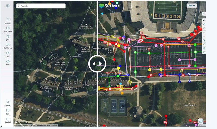
SiteMap® is GPRS’s proprietary GIS platform that shows you the hidden layers of your project. It’s a centralized record of every utility, structural element, and subsurface feature GPRS has collected on your project, available 24/7. Instead of hunting down old PDFs or chasing field reports, project teams can view, share, and collaborate on accurate site data from any device. Having a tool like SiteMap is the difference between quickly outdated deliverables and one living document.
Augmented Reality overlays subsurface utility data directly onto a live camera view of the job site. Where traditional ground penetrating radar (GPR) produces a marked-up slab or a plotted map, AR makes the invisible literally visible in real time, showing field crews and project managers exactly what’s below the surface before a single cut or core is made.
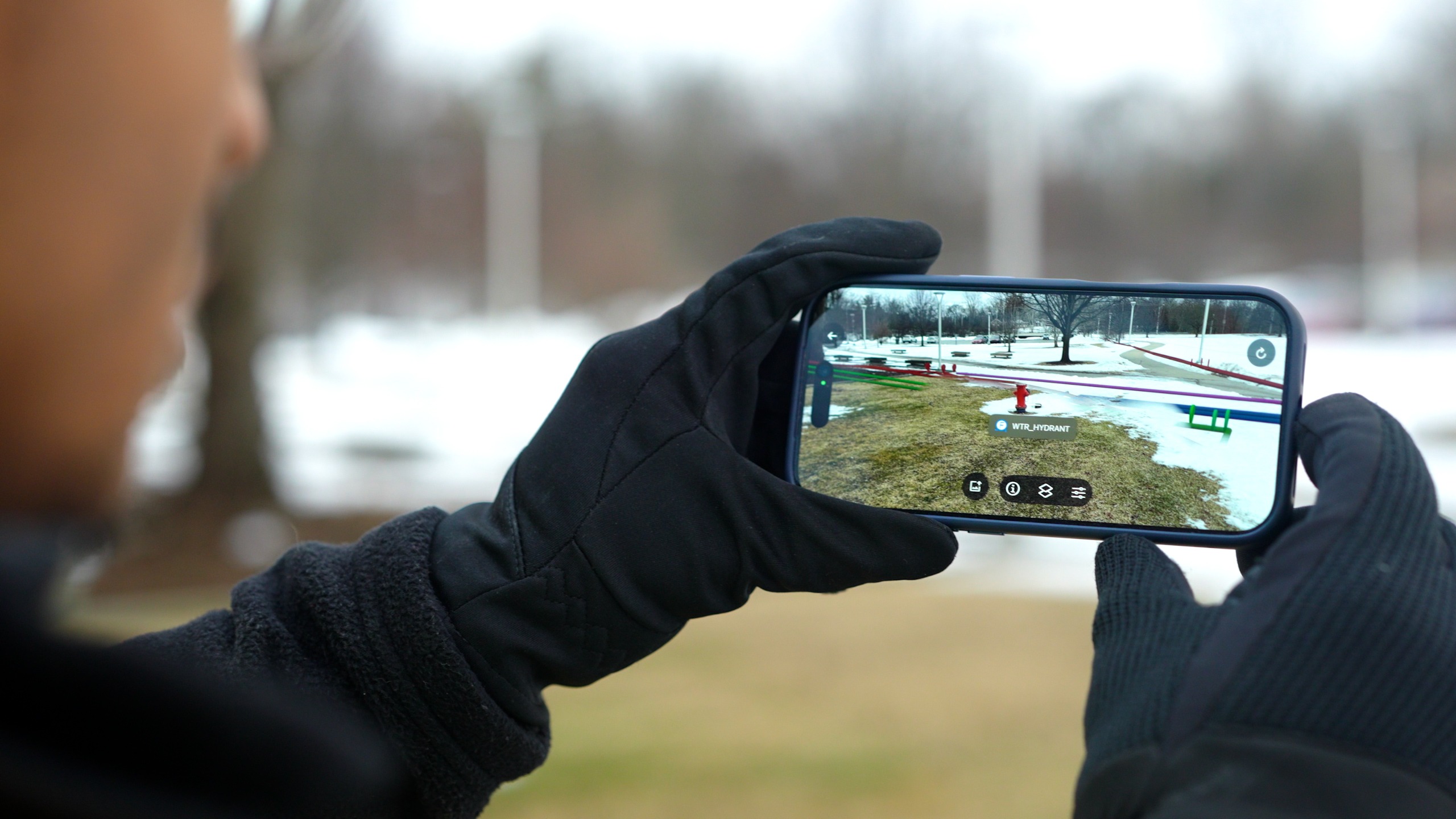
My Dig Board is a personalized dashboard within SiteMap that gives each user a consolidated view of their active projects, and site documentation, purpose-built for the way construction teams actually manage multiple jobs simultaneously. No more toggling between systems or waiting on someone else to pull a report.
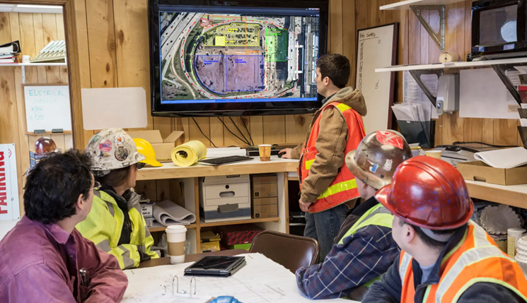
History Slider
The job history slider lets users compare two points in time from the same site view by dragging between an earlier scan and a current one to see exactly what has changed, what has been added, and what may have shifted. On multi-phased projects, that kind of visibility enables you to catch problems before they become costly change orders.
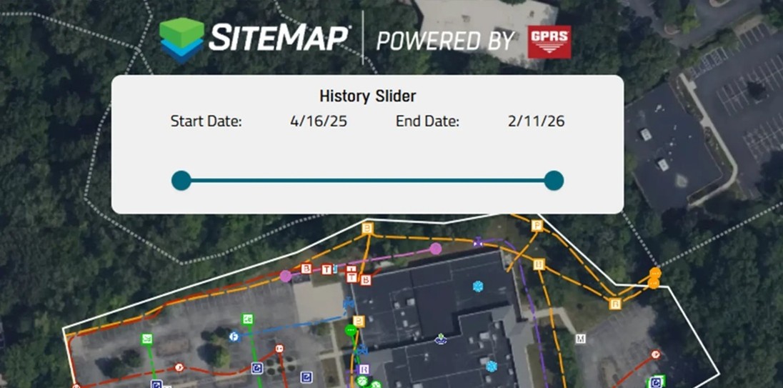
They Show Up Anywhere, Fast
It also means national reach with immediate local responsiveness. Growth-stage companies don’t always know where the next project is. A crew that can be on-site in a new region within 48 hours without the GC having to source, vet, and onboard someone new eliminates extra variables on already-complex jobs.
The Right Partners Help You Succeed on Every Project
When something goes wrong on a job site, nobody asks who the sub was. They ask who the GC was. Your subcontractor’s competence is your reputation on the line. That’s why the best partners invest in training programs that exceed minimum requirements, because their people’s performance directly determines whether your project succeeds. The right partners don’t just protect your projects. They protect your name.
Their Safety Culture Matches Yours
Which brings it back to safety. The best subcontractors don’t treat your safety standards as a ceiling. They treat them as the floor. A partner whose safety culture is as serious as yours means fewer problems on site. That alignment matters most on large or multi-phase projects, where a single incident can halt work, trigger audits, and follow a GC’s reputation long after the job is done.
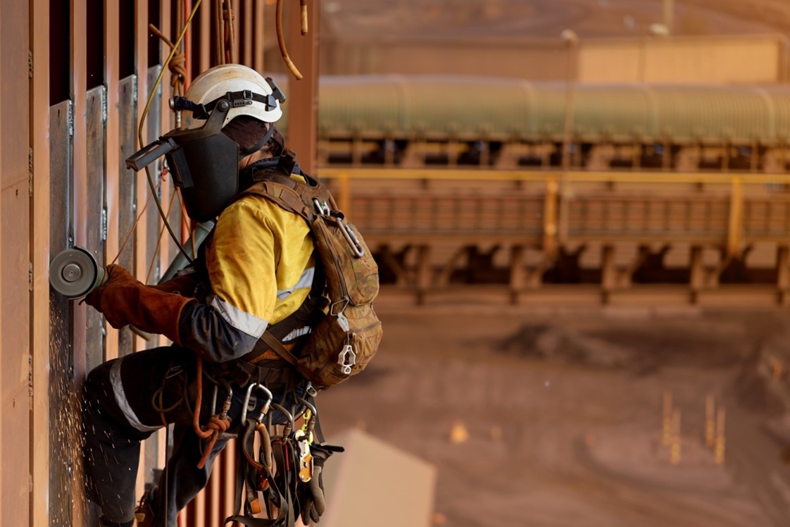
GPRS: Built to Grow with You
GPRS has built its model around these exact principles. With more than one million completed projects logged since the company’s founding and a 99.8% accuracy rate on utility locating and concrete scanning, GPRS brings SIM-certified professionals – holders of the industry’s most rigorous field credential – and nationwide coverage to every job. Whatever the scope, GPRS is built to carry you through each stage of growth, not just the stage you’re in today.
You standardized your fleet because consistency at scale is worth more than saving a few dollars per job. GPRS is built on the same principle.
Whether you’re running one site or a nationwide portfolio, call on GPRS to get the job done right. Click below to learn more and request a quote.
GPRS Pinpoints Steam Leak at New Orleans Trauma Center
The University Medical Center New Orleans, a Level 1 trauma center, was experiencing a steam leak that had puzzled its management team for roughly three months.
It was very important to find the leak using non-destructive methods so none of the medical center’s daily operations were disrupted.

They performed multiple dye tracing tests, which narrowed their search to a 250-linear-foot area. However, they still couldn’t pinpoint its exact position.
The ongoing issues also put the UMC at risk of temporarily shutting down to allow for extensive excavations. Because of this, the problem needed to be solved quickly.
That is where GPRS came in.
The medical center tasked GPRS Area Manager Steve Carney and Project Manager Justin Soileau with pinpointing the location of the steam leak.
GPRS Leak Detection Project Managers are trained to non-destructively locate leaks in pressurized water pipes. The process of locating a steam leak is no different, as it’s still water but in a different form.
Project Managers listen for leaks using acoustic leak detectors in conjunction with leak detection correlators to provide clients with the most accurate results.
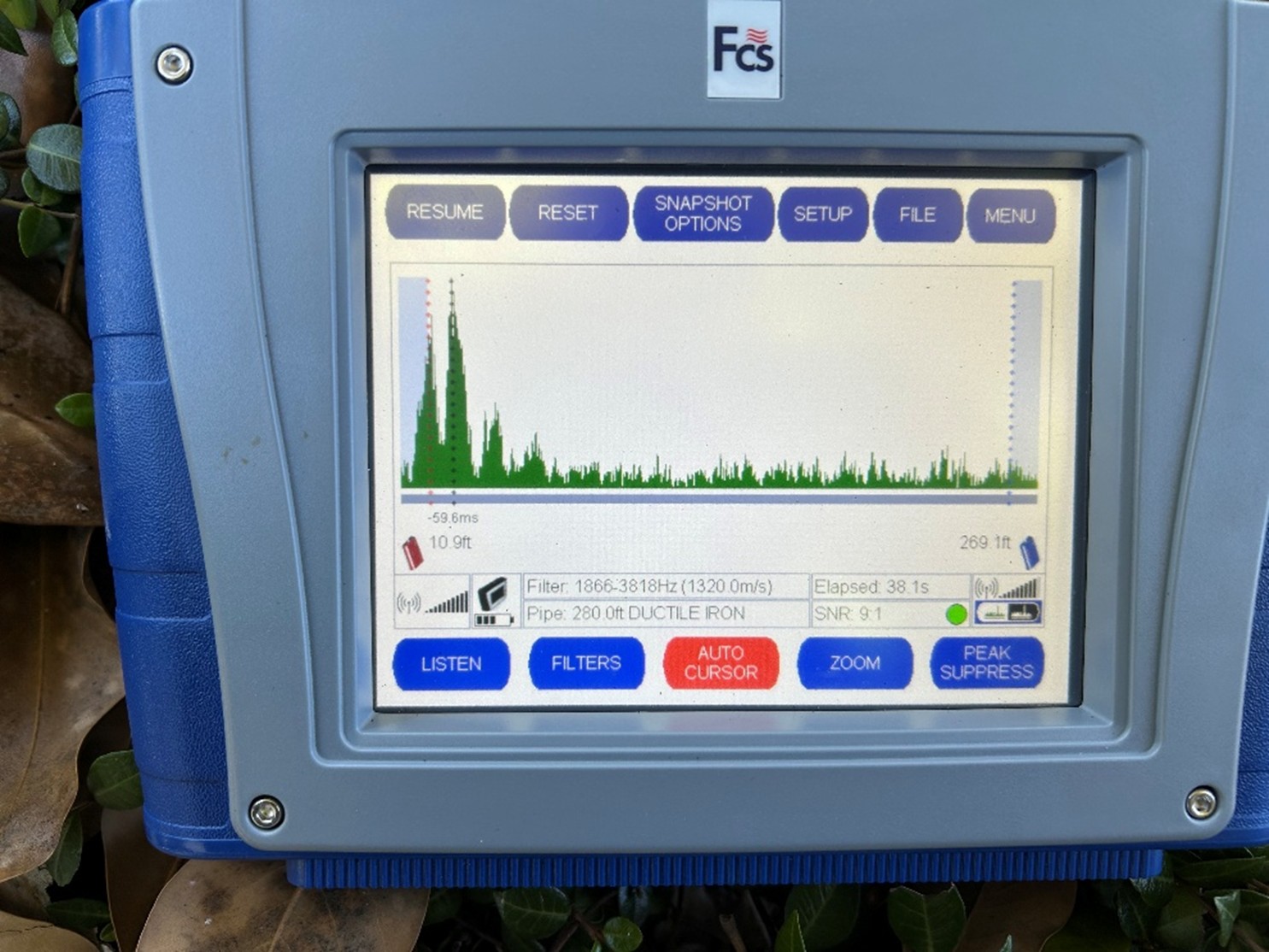
Carney and Soileau worked closely with the medical center to ensure they could access specific areas without interfering with the important work taking place behind the trauma center’s walls.
“The client led us to a pretty deep manhole that we had to get into to listen to the line,” Soileau explained. “And we had to run the correlations through the manhole, as well as inside of the mechanical room in both the buildings.”
Soileau has been with GPRS for over five years and all his time in the field along with his extensive training helped him find the elusive leak.
“This was textbook, as far as the job went,” Soileau explained. “It was super concise. The results of the correlators were perfect. We even matched up the drawings that the client provided to us with the mechanical joint and identified it as one of the failures.”
Once he located the leak, the UMC brought in A&A Mechanical to repair the steam line. To guarantee they could safely dig and not strike any other subsurface infrastructure, Soileau also located all neighboring utilities adjacent to the leak. When digging outside of a hospital, striking an underground utility, like a power or gas line, could cause service interruptions that would be detrimental to the safety of the patients.
Soileau documented his findings by marking the surface with spray paint, taking photos, documenting his results with GPS positioning, and uploading the utility scan data and leak detection report into SiteMap® (patent pending).
SiteMap is GPRS’ cloud-based GIS infrastructure management platform that securely houses our clients’ site data 24/7. Everything from 99.8% accurate utility data to 3D BIM models and NASSCO-certified reports can be uploaded into SiteMap and shared across teams to allow for better communication and smoother project execution.
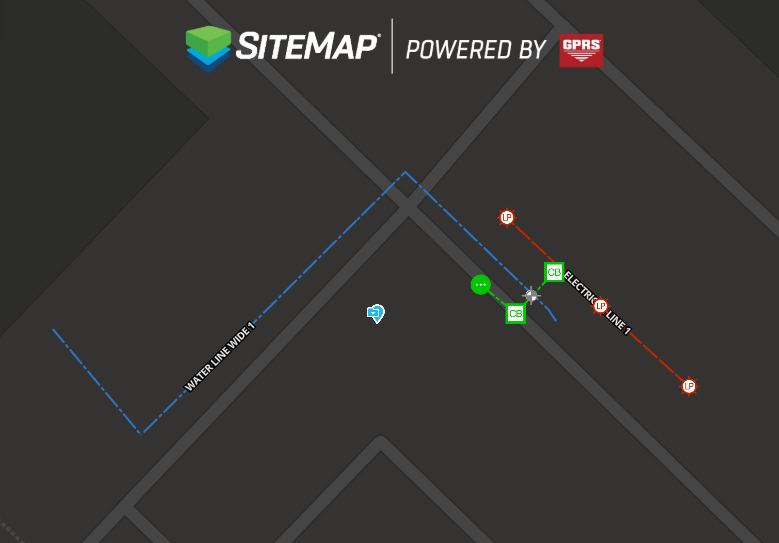
While performing the utility locate, Soileau discovered what he thought was the cause of the steam leak.
“There was a storm line in the area that we suspected was the cause of the issue,” Soileau explained. “The storm line had kind of caved in a little bit, and we believe that the soil that eroded from that may have caused the bend in the mechanical joint on that steam line and created the leak that they were experiencing.”
After delivering his results to A&A Mechanical, Soileau received the following message from an A&A Project Manager after the leak was successfully repaired: “We found that steam leak today. Exactly where you marked it. Great job! 14’ deep.”
Soileau was also very appreciative of Carney’s help throughout this project and wanted to make sure he expressed his appreciation for everything Carney does as an Area Manager.
“I wanted to give a lot of credit to Steve Carney. He wears multiple hats every single day. He was greatly involved in the front end of this, which contributed to a lot of the success of this job.”
From skyscrapers to steam lines, GPRS Visualizes the Built World®, above and below-ground, to make sure your projects stay on time, on budget, and safe.
What can we help you visualize?
FREQUENTLY ASKED QUESTIONS
What is SIM?
Subsurface Investigation Methodology (SIM) is a standard operating procedure and set of professional specifications that work as a guide for utility locating experts when scanning for buried utility lines. All GPRS Project Managers are required to achieve SIM 101 certification, which requires 80 hours of hands-on training in a classroom setting and 320 hours of mentorship in the field. For reference, the American Society for Nondestructive Testing’s (ASNT) minimum training recommendation includes eight hours for training and 60 hours practicing GPR to achieve NDT Level 1 certification in ground penetrating radar (GPR) scanning.
SIM requires the use of multiple, complementary technologies, like GPR scanning and electromagnetic (EM) locating, when locating buried utilities or scanning a concrete slab.
What is an annual leak survey and why do they matter?
An annual leak survey is a scheduled inspection of water infrastructure to identify and document leaks. These surveys are critical for regulatory compliance, environmental protection, and cost control. Regular assessments reduce water loss, prevent hazardous conditions, and extend asset life. For municipalities and facilities, annual surveys support proactive maintenance and budget forecasting.
How long does a leak detection usually take?
How long it takes to find your leak depends on the system size, complexity, and access conditions. A standard survey of a small facility or municipal segment may take several hours, while larger networks can require multiple days.
GPRS optimizes efficiency through pre-survey planning and site walks, real-time data collection, and advanced equipment, minimizing disruption and ensuring timely reporting.
Schedule GPRS leak detection services here.
Can GPRS determine the size of a detected leak?
GPRS determines the size of the leak by how far the leak signal travels between contact points and the pitch of the tone received.
GPRS does not, however, produce formal leak estimations.
GPRS Offers Free Construction Safety Week Training
GPRS is proud to sponsor Construction Safety Week. This year is the second in the five-year CSW plan “All In Together.” Register for your free CSW presentation here.
Construction remains one of the most dangerous U.S. industries. The “Focus Four,” also called the Fatal Four from the U.S. Occupational Safety and Health Administration (OSHA), make up most of the reported incidents on job sites:
- Falls
- Struck-by
- Caught-in/Between
- Electrocutions
Many add a fifth “fatal focus,” Silicosis, to this list, as well.
In the 2020s, falls have accounted for 35-37% of construction fatalities, struck-by accidents – meaning a worker was struck by a moving vehicle, heavy equipment, or falling objects – caused between 8% and 17% of deaths, electrocution by coming into direct contact with a live wire caused approximately 8% of fatal accidents, and caught-in/between machinery, equipment, collapsing structures, or materials make up 1-6% of all the work-related deaths.
The Center for Construction Research and Training, also known as CPWR, a nonprofit whose mission is to reduce occupational injuries, illnesses, and fatalities in construction, released statistics dating from 2011 through 2023 that show a continuing and alarming trend – a steady upward march in fatal construction injuries.
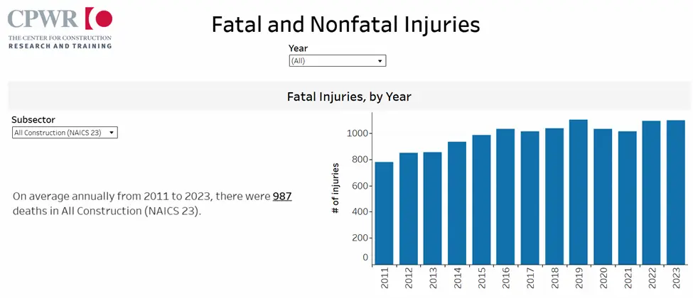
This data, as shared by Statista, among other data aggregators, finds that falls, slips, and trips far outpace other fatal incidents, with transportation accidents, fatal environmental substance exposure, and a combination of struck-by and caught-in/between accidents following.
The annual average numbers are stark:
- Falls, slips, and trips accounted for 364 serious injuries and deaths
- Transport accidents accounted for 259 serious injuries and deaths
- Environmental/Hazardous Material exposure accounted for 154 serious injuries and deaths
- Struck-by/Caught-in/Between incidents accounted for 148 serious injuries and deaths
- Personal violence accounted for 48 serious injuries and deaths
- Fires and explosions accounted for 13 serious injuries and deaths
That’s an average of 986 construction workers per year who don’t make it home safe at the end of their workday. 986 families whose fathers, brothers, sons, husbands, sisters, wives, daughters, and mothers are impacted by construction workplace safety.
At GPRS, we want everyone to make it home safe to their loved ones at the end of the day, every day. That’s why we are proud to sponsor Construction Safety Week.
This year, just like we have every year since 2019, GPRS safety professionals will fan out across the U.S. to give free, personalized CSW programs at job sites, in trailers, and in construction and subcontractor offices. No group is too big or small for our team to educate about the importance of a personal safety plan and how to stay aware of the hazards we deal with daily.
CSW’s theme this year is Recognize, Respond, Respect – part of its five-year push for greater awareness and safety across all contractors and trades – All In Together, A Five-Year Vision to Transform Safety.
- Recognize the presence and impact of High Energy/High Hazards/STCKY Activities
- Respond by putting direct controls in place
- Respect every hazard, every person, every life and every role in safety
GPRS is proud to help lead the charge for jobsite safety.
It’s not too late to book your team’s complimentary CSW presentation. Click the button below to register and schedule yours.
GPRS 2D and 3D Deliverables Help Set the Stage for 2026 NFL Draft Festivities
GPRS Project Manager Colton Carney once again proves that you never know where existing conditions visualizations may take you. He recently helped C3 Presents set the stage for one of the NFL’s biggest events - the NFL Draft at Acrisure Stadium in Pittsburgh, Pennsylvania.

In May of 2024, the NFL’s Fan Engagement & Major Events Advisory Committee selected the Pittsburgh Steelers to host the 2026 NFL Draft.
To host an event of this caliber, the event organizers needed to transform the 24-year-old stadium inside and out, so it can accommodate the players, families, and fans.
C3 Presents was hired to put together the green rooms within the stadium for the soon-to-be draft picks and their families to sit and wait to hear their names called. They also managed the hanging of large banners and needed to know the layout of piping runs before installing them.
To plan out the stadium’s draft day makeover, they needed precise measurements and models of the space. That is where GPRS came in.
In February of 2026, C3 Presents tasked GPRS Project Manager Colton Carney with scanning the inside of the Steelers’ home stadium, despite his allegiance to their AFC North rivals, the Cleveland Browns.

GPRS Reality Capture Project Managers utilize LiDAR-based 3D laser scanners to scan everything from skyscrapers to dinosaur skeletons and document the site’s existing conditions.
“It was approximately 15,000 square feet of scanning, and we did all color scans for that. Roughly 80 to 90 scans total,” Carney explained. “That entails capturing the data but also collecting high-def pictures.”
Each scan documented the stadium’s interior with millimeter accuracy and is automatically translated into a point cloud file.
Once Carney finished scanning the area, the point cloud was then converted into 2D and 3D deliverables by GPRS’ in-house Mapping & Modeling team.
“The modeling itself was focused on the floors, the ceilings, the walls, doors, windows, stairs, elevators, ramps, etcetera,” Carney explained.
C3 Presents received a collection of deliverables, including:
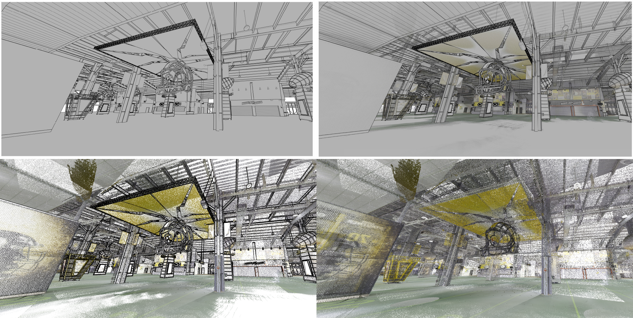
The precise drawings and models let C3 Presents make the best possible decisions throughout the project and ensure the location is ready for Draft Day. If only NFL executives could have this much certainty when drafting who they hope to be their next batch of franchise players.
In Carney’s four years as a GPRS Project Manager, he could confidently say this was a job he’ll never forget.
“I thought it was an awesome experience,” Carney explained. “I didn’t know that what we do every day was even involved in that process. But this is definitely the coolest job that I've done.”
Months later, while watching the 2026 NFL Draft, Carney had a whole new perspective watching this annual sport event he had been watching for many years.
“It's pretty awesome to see the players and their families knowing that that the entire layout and floor plan of what they came up with for them and say it was from the data that we had collected that day,” Carney explained.
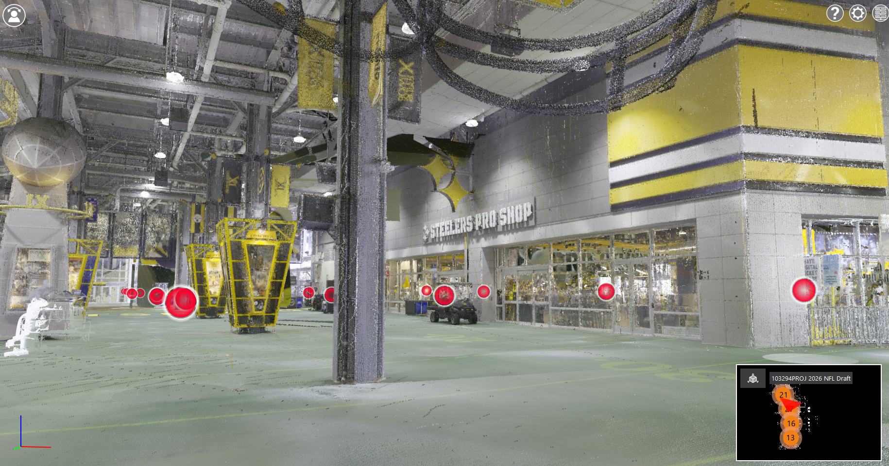
From stadiums to sewer lines, GPRS Visualizes the Built World, above and below-ground.
What can we help you visualize?
FREQUENTLY ASKED QUESTIONS
WHAT IS LIDAR?
LiDAR (Light Detection and Ranging) is a remote sensing tool that builds accurate 3D models of objects and surfaces.
Instead of using radio waves like radar, LiDAR sends out laser pulses from a scanner. These light pulses bounce off objects, and the system measures how long they take to return. This helps calculate exact distances and shapes. It creates detailed three-dimensional data about an object.
Learn more about LiDAR and how GPRS utilizes LiDAR laser scanners here.
WHAT IS POINT CLOUD DATA?
Point cloud data is the term for data points collected by LiDAR-based laser scanners.
Each point stores X, Y, and Z coordinates for visible surfaces like walls, doors, and MEP components.
The data points are used by GPRS’ in-house Mapping & Modeling team to create 2D and 3D deliverables for clients.
Learn more about GPRS’ Point Cloud Services here.
WHAT IS SIM?
Subsurface Investigation Methodology (SIM) is a standard operating procedure and set of professional specifications that work as a guide for utility locating experts when scanning for buried utility lines. All GPRS Project Managers are required to achieve SIM 101 certification, which requires 80 hours of hands-on training in a classroom setting and 320 hours of mentorship in the field. For reference, the American Society for Nondestructive Testing’s (ASNT) minimum training recommendation includes eight hours for training and 60 hours practicing GPR to achieve NDT Level 1 certification in ground penetrating radar (GPR) scanning.
SIM requires the use of multiple, complementary technologies, like GPR scanning and electromagnetic (EM) locating, when locating buried utilities or scanning a concrete slab.
WHAT REALITY CAPTURE DELIVERABLES CAN GPRS PROVIDE?
GPRS can deliver point cloud data in many formats, including:
We can also deliver the following customizable deliverables upon request:
- Aerial Photogrammetry
- Deformation Mapping
- Digital Drawings of GPR Markings
- Floor Flatness Analysis / Contour Mapping
- At-Depth Modeling
- Native Modeling
- New Construction Accuracy Analysis/Comparative Analysis
- Point Cloud Modeling Training Webinars
- Reconciliation of Clients 2D Design Drawings
- Reconciliation of Clients 3D Design Model
- Structural Steel Shape Probability Analysis
- Template Modeling
- Volume Calculations
Schedule a service with our Reality Capture Project Managers here.
Structural and Subsurface Data Supports Substation Upgrades
GPRS’ 99.8% accurate underground utility and concrete scans, along with millimeter-accurate 3D laser scans, provided an electrical contractor with the confidence to conduct infrastructure upgrades at a substation.
An electrical contractor was selected to upgrade the overhead feeder lines into the substation along the main access road, requiring the replacement and relocation of utility poles.
They required a full-site 3D visualization of above and below-ground conditions.
The scope included as-builts of the pole locations, overhead lines, and nearby infrastructure, as well as interior scans of the on-site office building.
The electrical contractor also needed to perform tie-ins inside the office building and had no existing as-builts of conduit, rebar, or post tension cables inside the mechanical and storage rooms.
That’s where GPRS came in. GPRS Project Manager Matthew Caerulius completed two days of utility locating across this 127,000 square feet jobsite.

“I conducted utility locating [on the first day], which we started with the front parking area and the roadway that heads up to the main road,” Caerulius explained. “I started scanning there and focused on that area plus the connecting road to the main yard where the electrical building is located.”
Caerulius utilized ground penetrating radar (GPR), electromagnetic (EM) locating, and a traceable rodder to identify and mark underground utilities across the site.
As with all GPRS Project Managers, he is trained in Subsurface Investigation Methodology (SIM). SIM is a standardized operating procedure and set of professional specifications that guide the utility locating process for buried infrastructure. SIM sets the required field standard for all GPRS Project Managers and Field Team members.
This methodology ensures consistent results and supports GPRS’ industry-leading 99.8% accuracy rate across hundreds of thousands of scans.
.webp)
Then, after the snow melted, he re-marked the utilities on day two to maintain clear reference points for the 3D laser scanning scope.
As a next step, Caerulius located utilities throughout the main yard surrounding the electrical building. He noted, “What stuck out to me was a large amount of the electrical network we picked up from that main building. There were a lot of connecting lines.”
That level of underground congestion highlighted how critical 99.8% accurate utility data was to prevent conflicts and keeping the client’s upgrade work on track.
To keep a permanent record of the temporary utility markings, Caerulius used GPS positioning to create a digital map of his findings and uploaded the data into SiteMap® (patent pending) so the client could access it right away.
.webp)
On day three, concrete scanning and reality capture were completed, covering 127,000 square feet of bare earth, structural features, aerial infrastructure, and existing powerlines. Color laser scanning delivered high-resolution point clouds that clearly documented utility markings and site details, enabling accurate interpretation and confident decision-making.
For the reality capture scope of work, Remond and Blake were tasked with utilizing multiple terrestrial 3D laser scanners to scan across the long road to the main highway.


Remond used a long-range 3D laser scanner to keep the scan data level across the vast jobsite.
This LiDAR laser scanner captured detailed information about the ground in a georeferenced point cloud, including grassy areas and hills. “So, the [long-range scanner] kept everything level, and captured longer, more accurate [measurements] over the longer distances,” said Remond.
This technology enables precise elevation mapping and realistic surface modeling, even across complex terrain, providing a comprehensive digital representation of existing site conditions.
%20(3).webp)
These scans were in color, allowing the contractor to see the utility markings on the ground.
“So, it was a unique project where I was working directly with [Caerulius] to coordinate with him where he needed to touch up lines, and what lines were still good to scan. My role with the laser scanner was to precisely document where the utility lines were,” explained Blake.
Caerulius used ground penetrating radar (GPR) to conduct a concrete scan of the office building and visualize conditions within and beneath the slab-on-grade.
Once the concrete scanning was finished, Blake performed colorized 3D laser scans to document the concrete markings.
He stated, “I just had to lower the scanner to make sure I was seeing under there. Some of the markings went under the table. So, I had to make sure I was getting scans at different angles.”
To capture the full extent of the markings, Blake adjusted the scanner’s position differently than he would for a standard architectural scan to obtain clear visibility of the floor and ensure full coverage of all the marked areas.
As Blake explained, “I made sure I backed up and put the scanner in a spot where it would see the ground from the previous spot, just so that there weren’t any holes in the floor’s data.”
Thanks to GPRS’ comprehensive visualization services, both above and below-ground, the electrical contractor prevented costly overruns, saved time, kept their workers safe, and avoided subsurface damage during construction.
From substations to subsurface mapping, GPRS Visualizes the Built World to keep your projects on time, on budget, and safe.
What can we help you visualize?
Frequently Asked Questions
What deliverables are part of a GPRS utility locate?
A GPRS utility locate can include field markings, flags, and digital records of the utilities located on site. The common deliverables include complimentary PDF and KMZ utility maps, depths where possible, along with georeferenced utility data via the SiteMap GIS platform and mobile app. You can also export, share, print, or download 2D CAD drawings, and 3D BIM or conceptual models from GPRS’ Mapping & Modeling Team.
See how GPRS converts 99.8% accurate utility locate data into georeferenced, shareable deliverables that support excavation planning, site coordination, and enhance jobsite safety, here.
What is the difference between GPR and EM locating?
GPR and EM locating find underground utilities in different ways. GPR uses radar to detect subsurface elements underground or within a surface, while EM locating detects the electromagnetic signals from pipes and cables. GPRS’ SIM-certified Project Managers often use both methods together, with each technology used to verify the other and confirm the accuracy of the findings.
Learn more in Utility Locating: Electromagnetic Locating, Utility Locating Services Explained, GPR Explained, and SIM Explained.
How long does 3D laser scanning take?
Most on-site 3D laser scanning takes a few hours to a few days, while large campuses or facilities can take longer. The schedule depends on the size of the site, the required scan density, line-of-sight conditions, and the deliverables needed after capture, such as point clouds, 2D CAD drawings, 3D BIM models, or virtual tours. We define the scope first, capture the site with LiDAR-based scanners, and then process the data into the formats your team needs for planning, design, and coordination.
Learn more about GPRS’ 3D Laser Scanning Process, here.
What is at-depth modeling?
At-depth modeling is a Revit-based 3D model that depicts subsurface utilities and concrete obstructions at their measured depths below the surface. GPRS’ Mapping & Modeling Team creates at-depth structural and subsurface 3D models with utility locating, concrete scanning, and 3D laser scan data, so you can understand how below-ground conditions relate to the site above. GPRS’ Project Managers locate subsurface features with GPR and EM and capture site geometry with LiDAR. Then, GPRS’ Mapping & Modeling Team converts those findings into an integrated 360° visualization that is accessible via SiteMap.
Learn more about At-Depth Modeling and how it can help your project, here.
What Is Ground Penetrating Radar (GPR)? Cost, Uses & Safety Guide
What is Ground Penetrating Radar (GPR)?
A Cost and Safety Guide for Modern Contractors
For today's general contractors, technology is no longer optional. It's the difference between staying on schedule and facing costly delays. One of the most important tools reshaping construction and subsurface investigation is ground penetrating radar (GPR).
Whether you're planning a core drill, trenching utilities, or managing a complex commercial build, understanding GPR scanning can help you avoid risk, improve efficiency, and deliver better outcomes.
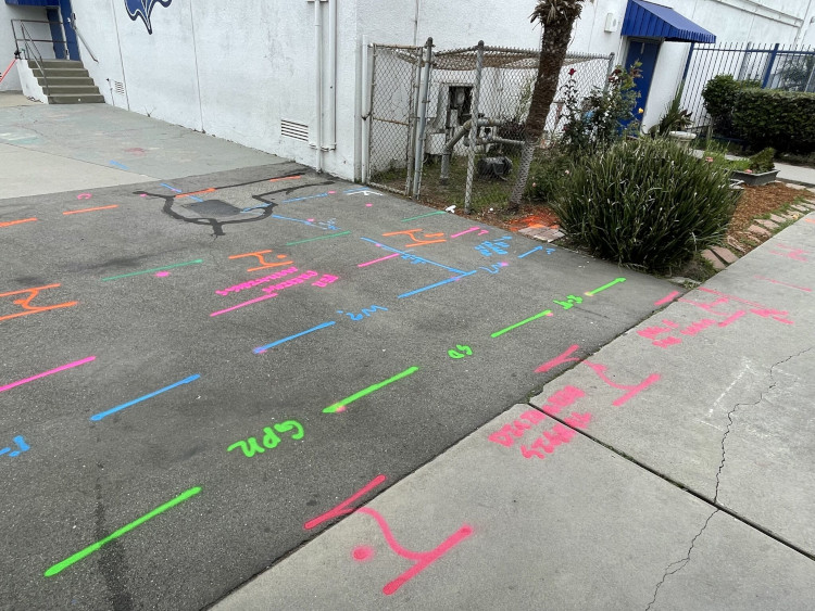
What is Ground Penetrating Radar (GPR)?
Ground penetrating radar (GPR) is a non-destructive technology that uses electromagnetic waves to detect objects beneath the surface. These signals are transmitted into materials like concrete or soil and reflect when they hit something, such as rebar, conduits, or underground utilities.
According to the Common Ground Alliance, utility strikes cost the U.S. more than $30 billion annually in direct damage costs alone, with an additional $61 billion in waste and excess costs. That number makes one thing clear: knowing what's underground before you dig isn't a luxury. It's a financial and safety imperative.
The system measures two key things:
- Time: Determines depth
- Amplitude: Indicates the strength of the signal and helps identify material differences
This allows technicians to map subsurface features without cutting, drilling, or excavating. In practical terms, ground penetrating radar utility locating helps contractors see what's below before they break ground.
Why GPR Matters for Contractors
If you're relying only on drawings or 811 markings, you're leaving gaps in your coverage. Many contractors don't realize more than 65% of buried utility lines on any given site are unregistered private utilities that 811 does not locate. That means the majority of what's underground is invisible to the standard call-before-you-dig process.
Hitting one of those lines can mean project shutdowns, crew injuries, and liability exposure.
GPRS, on the other hand, will not only verify all public and private lines, but we will also confirm any existing 811 mark-outs as part of every utility locate that we perform, giving you double verification backed by our 99.8% accuracy rate.
Here's where GPR becomes critical:
- Prevents damage to post tension cable, rebar, and conduits
- Reduces risk during concrete scanning services
- Improves accuracy in utility mapping
- Helps avoid costly change orders and delays
For contractors, using tools like GPR isn't just smart. It is the industry standard for general contractors who hope to win business in today’s construction market.
Key Applications of GPR in Construction
1. Concrete Scanning Before Cutting or Drilling
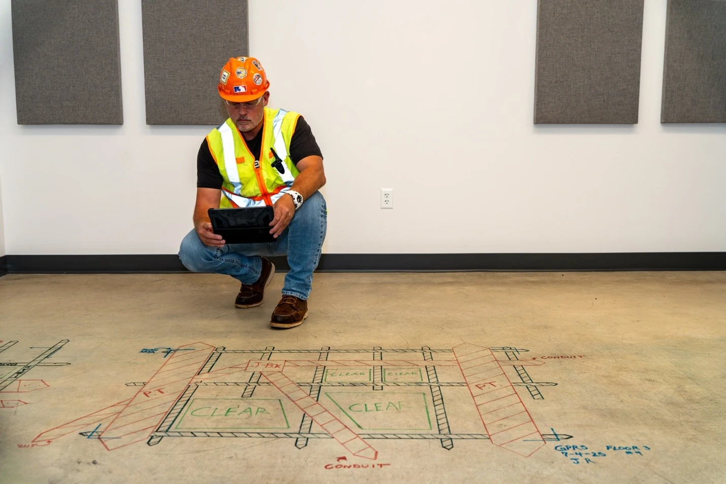
Before performing core drilling or anchoring, contractors rely on concrete scanning to locate embedded objects.
GPR can identify:
- Rebar and wire mesh
- Conduits and pipes
- Post-tension cables (critical to avoid cutting)
- Slab thickness and beam locations
A typical scope of work includes scanning a defined area around planned drill points, marking safe zones, and identifying hazards. This is essential for core drilling, anchoring systems, and saw cutting.
GPR scanning helps you avoid structural damage, injuries, and project delays that could result from striking a post-tension cable
2. Utility Locating Before Excavation
GPR is commonly used alongside electromagnetic (EM) locating tools to trace conductive utilities, identify unknown or undocumented lines, and support comprehensive ground penetrating radar utility locating processes. Unlike public 811 services, which only mark lines up to the meter, GPR helps GPRS locate private electrical lines, water and sewer connections, and communication infrastructure running through privately owned property. This makes it a key component of utility mapping on commercial job sites.
3. Trenching and Directional Boring
For trenching and horizontal directional drilling, depth accuracy is critical. GPR helps contractors identify utilities crossing the trench path, estimate depth to avoid strikes, and plan safer drilling routes. In directional boring, where the drill head is not visible, combining GPR with potholing significantly reduces risk.
4. Subsurface Void Detection
Voids beneath concrete or soil can lead to structural failure. GPR can detect potential air gaps beneath slabs, soil erosion zones, and potential sinkhole conditions. While it identifies the extent and starting depth, it typically cannot measure full void depth, something contractors need to factor into planning.
5. Integration with Other Services
GPR is often part of a broader subsurface strategy. It works most effectively when combined with video pipe inspection for internal pipe condition assessment, acoustic leak detection tools for locating water loss, and CCTV drainage surveys that confirm external soil and pipe conditions. For example, a water leak detection company may locate a leak acoustically, then use GPR to map surrounding utilities before excavation begins. This layered approach provides a far more complete picture of subsurface conditions than any single technology alone.
What Affects GPR Performance?
GPR is powerful, but it's not impervious to environmental conditions. Its effectiveness depends on several real-world factors.
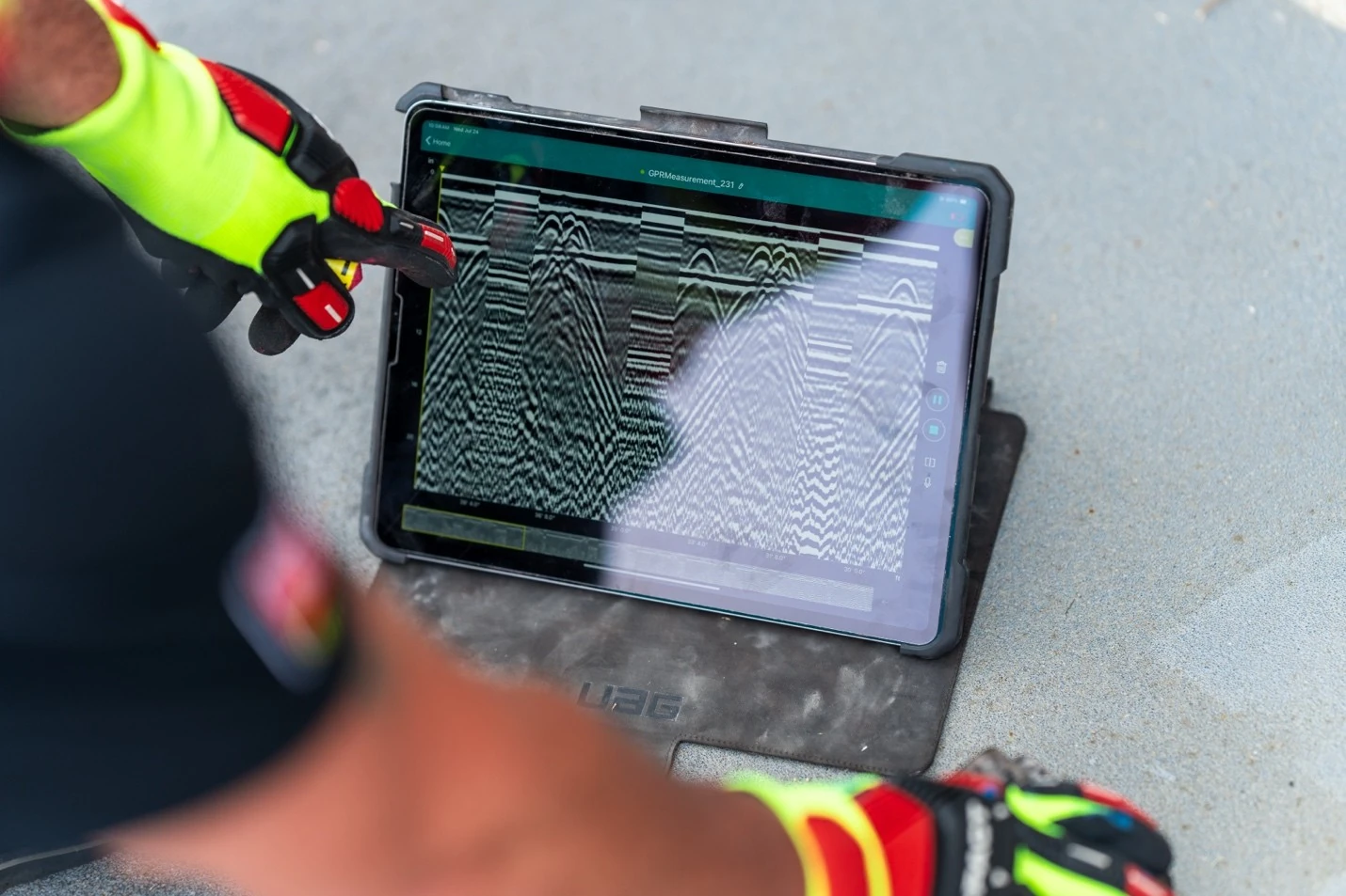
Material Type: Dry sand and concrete allow excellent signal penetration, while wet clay or dense materials reduce signal strength and limit depth.
Depth Limitations: Higher frequency antennas (around 2 GHz) offer better resolution but less depth. Lower frequency antennas (around 400 MHz) reach greater depths but with less detail, making antenna selection a key part of any pre-scan assessment.
Slab Conditions: Thick slabs over 16 inches may require scanning from both sides. Newly poured concrete may limit visibility, and reinforcement like steel fibers can obscure signals.
Surface Conditions: Certain finishes like terrazzo can affect readings. Pan decking and hollow core slabs require special interpretation.
Understanding these limitations is key to using GPR scanning effectively on the job site.
GPR vs. Other Subsurface Technologies
GPR is not a standalone solution. It's part of a toolkit.
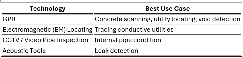
For example, sewer inspection often relies on video pipe inspection, not GPR. Leak detection service providers may use acoustics first, then GPR for mapping. The best results come from combining these methods.
GPR for Modern Contractors: A Competitive Advantage
For newer contractors entering the field, adopting technologies like GPR can set you apart.
- Improved safety: Fewer utility strikes
- Better planning: Accurate subsurface data
- Client confidence: Professional, tech-enabled workflows
- Cost control: Reduced rework and delays
Even if you're not operating the equipment yourself, understanding how GPR works helps you ask the right questions, interpret results, and coordinate better with service providers.
Should You Rent, Buy, or Hire GPR?
When a project requires GPR, contractors generally have three options: rent the equipment, buy it, or hire a professional. Here is what each one costs.
Renting GPR Equipment
Renting a utility locating GPR unit runs approximately $400–$1,750 per month. A handheld concrete scanning unit rents for roughly $1,000–$4,000 per month. Those figures cover the equipment only. A complete utility locate also requires an electromagnetic (EM) locator, which rents for about $700–$1,500 per month, plus a rodder/sonde combination at around $250 per month to detect non-metallic pipes. Renting only makes financial sense if you already have staff trained to operate the equipment and interpret the data. Without that training, the results are unreliable regardless of the equipment.
Buying GPR Equipment
A utility locating GPR unit costs between $14,000 and $100,000 to purchase, depending on features. An EM locator adds $800–$5,000. A rodder adds $975–$3,000. Total average cost to own a full utility locating setup: $65,000, plus training.
For concrete scanning, a handheld GPR unit costs $11,000–$17,000. Add a tablet to read the data and the total system runs up to $15,000, plus training.
Training is a separate cost either way. A basic online GPR course runs about $600 and does not meet minimum industry certification standards. A Level 1 NDT certification requires eight hours of classroom time and 60 hours of field practice, at approximately $1,000 per person per level.
Buying equipment makes sense for companies that do this work constantly and have trained staff to run it.
Hiring a Professional GPR Service
For most contractors, hiring a professional is the more accurate and cost-effective path. GPRS Project Managers are SIM-certified, which requires 80 hours of classroom training and 320 hours of field work. That is more than three times the industry minimum. It is the reason GPRS has maintained a 99.8% accuracy rate across more than 350,000 projects. You get the right equipment for your specific job, operated by someone who knows how to read the results, without the capital outlay or the training burden.
The Role of GPRS in the Industry
Companies like GPRS have built our services around combining GPR with other technologies to deliver full-site visibility. With capabilities spanning concrete scanning, private utility locating, utility mapping, video pipe inspection, and leak detection, GPRS offers a comprehensive approach that aligns with how modern construction projects are managed.
What sets us apart is our use of SIM-certified Project Managers trained under Subsurface Investigation Methodology, the industry's most rigorous standard for subsurface investigation. SIM certification requires 320 hours of mentored field training and 80 hours of classroom work, far exceeding the typical industry recommendation of just eight hours of classroom time and 60 hours of practice.
That investment in training is why GPRS has maintained a 99.8% accuracy rate in utility locating since 2017. For contractors, it means fewer blind spots, fewer surprises, and a partner you can rely on when a client asks how you knew the site was safe.
Ground penetrating radar has become a cornerstone of modern construction planning. From concrete scanning to utility locating, it provides the insight contractors need to work safely and efficiently.
Click below to see how GPRS delivers safer, faster workflows for construction professionals.
How SiteMap 3.0 Enhances Project Planning and Management
Without dependable information, general contractors, superintendents, and facility managers can’t plan and execute projects effectively. Too often, critical site information is scattered across different physical or digital environments.
If the data needed isn’t readily available, costly mistakes and project delays are inevitable.
SiteMap® 3.0 solves this problem by giving your team a single source of truth with additional features that enhance your ability to access and share your important site records.
What is SiteMap 3.0?
Released in February of 2026, SiteMap 3.0 is the third major update to the platform since its initial launch in 2021. The new features stemmed from listening to SiteMap users and learning how to best serve their needs.
Before the addition of the 3.0 update, the SiteMap platform had already supported various features, including:
- GPRS utility data from 2021 onward
- Utility layers
- Drone imagery
- CADD imports
- Geolocated floor plans
- Emergency evacuation routes
- Reality capture models
- Sewer inspection records
And the SiteMap 3.0 update added the following features:
- SiteMap Mobile Augmented Reality
- My Dig Board
- Customer Self Service Form
- Feature Name & Style Customization
- History Slider
Augmented Reality: Uncover What’s Below Your Feet
Utility strikes continue to cause billions of dollars of damage every year. Markings on the ground from utility locating professionals help deter the issue, but what if you could see where your utilities are buried right in front of you?
That can become your new reality with SiteMap Mobile’s new Augmented Reality feature.
By using the mobile app on your phone or tablet, users can stand on site and view their subsurface utilities above ground.
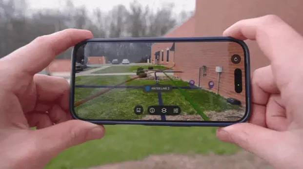
GPRS Director of Digital Product and Delivery Brian Skelding had this to say when asked about the augmented reality feature:
“It’s not just a ‘wow’ feature; it’s a practical feature. Clients are using this in a real demonstrated way, so that they can understand, ‘wow, my infrastructure really is right there – I’m going to have to make adjustments.’”
By having RTK-positioned AR utility views at your fingertips, you can reduce guesswork and manage a safer job site.
My Dig Board: Your Mobile Job Trailer
After the 6AM meeting in the trailer, workers can lose or forget some information throughout the workday. And if change orders arise, how do you communicate those changes to your whole team?
All those headaches are now avoidable with My Dig Board.
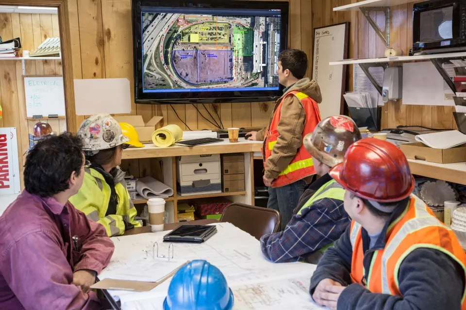
This feature allows users to create markups using polygons, arrows, and text to visualize:
- Delivery areas
- Drop zones
- Staging spaces
- Traffic barricade locations
- And whatever else you need to communicate
Because of the capabilities of My Dig Board, SiteMap changes from a platform that only collects and displays GPRS field-verified data into an interactive digital map that clients can use to communicate across teams.
And if the plans change throughout the project, if you update My Dig Board, your whole team can see that update and stay on the same page. Your one-stop shop to plan, communicate, and manage your work better.
Customer Self Service Form: Request Additional GPRS Services Directly
Constant phone calls and emails can slow the production of a project. When teams need additional services to keep jobs on schedule, time is of the essence.
That is why we created the Customer Self Service Form within SiteMap.
Like My Dig Board’s interactive features with your team, the Customer Self Service Form allows you to directly interact with our GPRS team and request additional services.
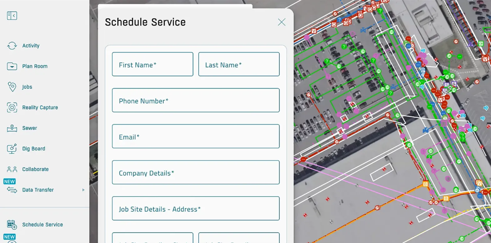
To schedule additional GPRS services, you can now open the self-service form on the platform, request the services you need, and even show where you need the service performed on the satellite image of your site.
No need for phone tag or email chains.
The services you can request with the Customer Self Service form include:
- Utility / UST Locating
- Concrete Scanning
- 2D / Floor Plan Modeling
- 3D / BIM Modeling
- GIS Mapping
- 3D Laser Scanning
- BOMA Measurements
- Drone Imaging
- Virtual Walkthrough
- Mainline / Lateral Inspections
- Leak Locate / Survey
Customize SiteMap YOUR Way
Visual clarity is crucial when managing big projects with large groups of people. Without it, mistakes can occur that lead to hefty costs and serious injuries.
Instead of learning a whole new mapping system, SiteMap 3.0 now lets subscribers rename features and customize the utility lines as they appear on site.
Everything from power sources to irrigation lines can now be renamed to match your internal records. By tailoring your SiteMap experience to your established naming system, record keeping remains consistent and clear so projects can move forward more efficiently.
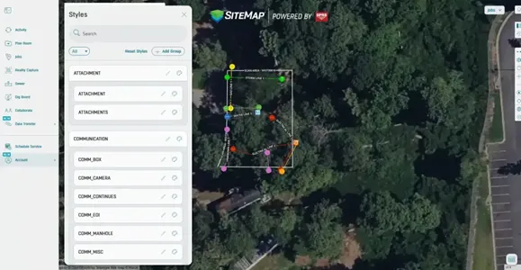
And when customizing the utility line styles in SiteMap, you can change the colors, line styles and line thickness to match your current records.
A map that is hard to read or analyze is practically useless, so this level of customization allows for clarity in the field and the meeting room. Your team will spend less time hunting for critical information and make fewer mistakes.
History Slider: Travel Through Time in Your Digital Site
If you manage large facilities or campuses, analyzing the map of all your underground utilities can feel overwhelming.
When preparing for your next project, where do you start? What if you only want to see utility data from the last year? Or from February through May of 2023? The new History Slider helps you do exactly that.
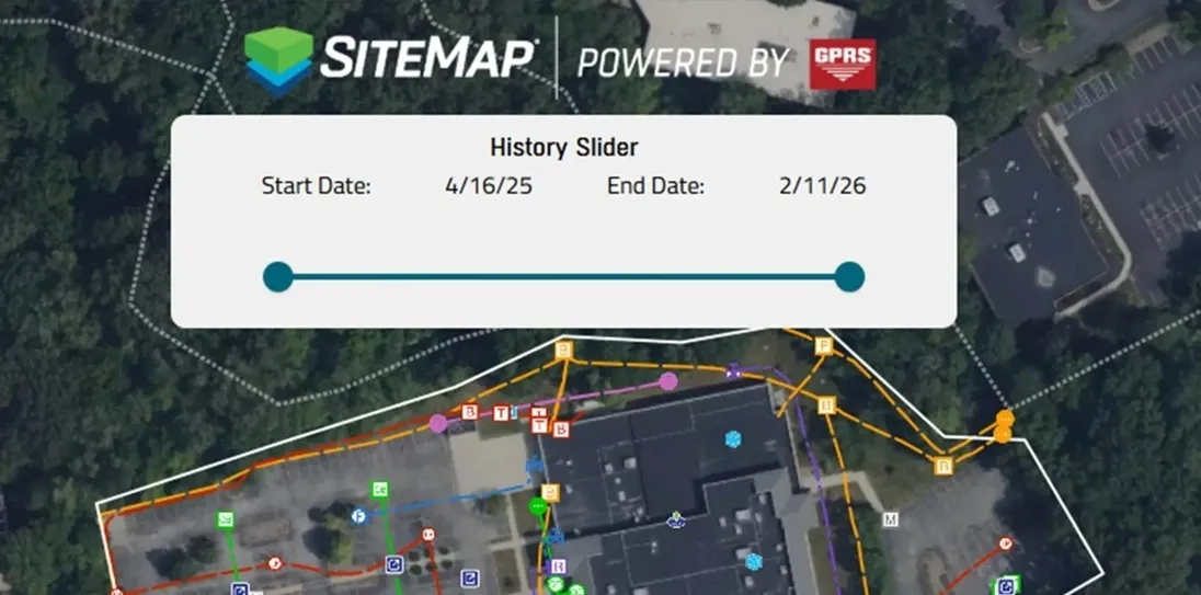
The SiteMap platform includes records from as far back as 2021. As site records expand over time, it’s crucial to understand how your site has changed.
While general contractors on site may only need recent locates, facility managers would need older records too so they can completely understand their site.
The filtering capabilities support audits while also enhancing the planning process and record checks through better organization and clarity.
Why Does SiteMap 3.0 Matter to Me?
With the features launched in its third major update, SiteMap transformed from a one-way delivery system into a two-way working platform. Your utility map is now fully customizable without losing any data accuracy or speed in delivery.
Our SiteMap team built each new feature from real client feedback and assessed the pain points they face every day.
For facility managers and their teams, they can access all the information securely in one place, removing the risk that scattered records bring.
For GCs and supers, work remains on time, on budget, and safe without the consequences of using unclear or inaccurate information.
Eliminate surprises on your job site and execute your projects with confidence with SiteMap 3.0.
See it in action by booking a FREE demo here.
FREQUENTLY ASKED QUESTIONS
How do contractors and subcontractors utilize SiteMap?
Contractors and subcontractors use SiteMap to securely access and share current site information in the field.
That includes layered utility maps, NASSCO-certified sewer reports, CADD/BIM files, and mobile access that help teams coordinate excavation and trade handoffs.
GPRS supports project workflows by delivering field-verified data through SiteMap, including mobile augmented reality and My Dig Board so crews can visualize utilities, communicate dig plans, and keep updates visible to the whole team.
ENR reported on how Power Construction used the SiteMap mobile app on a $389 million Illinois hospital expansion to verify utility depth in the field and adjust work based on real subsurface conditions.
How does GPRS contribute to jobsite safety in construction?
GPRS Project Managers contribute to job site safety by helping teams identify subsurface utilities and structural reinforcements before they dig, cut, or core.
Utility strikes are still a major risk on site. Data collected by the Common Ground Alliance (CGA) showed 196.977 utility damages reported in 2024.
We help reduce that risk through utility locating, concrete scanning, video pipe inspection, and digital as-builts delivered via SiteMap.
How do I export data from SiteMap?
Clients can export SiteMap data in formats that fit multiple workflows. SiteMap supports exports such as DXF, Shapefile, GeoJSON, and KML/KMZ. And users can export the current map view or a selected area drawn around the portion of the site.
The platform makes that process straightforward through built-in export tools.
In our “SiteMap Feature Friday: How to Export Your Data” webinar, our team demonstrates how clients can move verified utility records out of SiteMap and into other design and planning platforms.
Can SiteMap scale as my portfolio grows?
Yes. SiteMap is designed to scale from a jobsite to a multi-site or campus-wide portfolio.
The platform centralizes utility maps, CADD/BIM files, drone imagery, and sewer records in one secure system that can be accessed across teams.
GPRS supports that growth by collecting above and below-ground site data, providing controlled sharing, and keeping information available 24/7 on desktop and mobile devices.
During a massive job with the University of Toledo, GPRS uploaded the utility data gathered across over 112 acres into SiteMap. After nearly two months of continuous scanning, GPRS gave the school a complete map of all buried infrastructure across its entire campus. This is one of the many instances that demonstrates how the platform supports larger facility portfolios over time.
What is the Cost of Utility Locating?
How Much Does Private Utility Locating Cost?
GPRS Private Utility Locating Costs Explained
When it comes to the cost of utility locating, the most important thing to know is this: with GPRS, you only pay for what you need, and investing in accurate utility locating services saves you far more than it costs.
You can always count on GPRS for straightforward, upfront utility locating pricing built around your project goals and timeline, so you never pay for services you don’t need.
GPRS tailors every utility locating quote by project scope because every building and site are different. Utility locating pricing depends on several factors, including:
- Soil conditions
- Site size
- Utility depth
- Number of utilities present
- Night/weekend work
- Level of detail required
- Deliverables required
GPRS provides pricing based on your specific site and project needs, not a one‑size‑fits‑all rate.
What You Get with Every Utility Locate
GPRS Project Managers locate, mark, and map all subsurface utilities using ground penetrating radar (GPR) and electromagnetic locating (EM) technology prior to excavation to help prevent strikes, protect your crew, and avoid costly damage and delays.
Comprehensive Subsurface Utility Detection
You will receive on site field markings with spray paint and/or pin flags, color-coded to American Public Works Association standards, plus utility maps to give your team a clear understanding of the exact location, depth, and layout of all underground utilities on your job site, including:
- Electric power lines, cables, conduit and lighting cables
- Gas, oil, steam, petroleum, and gaseous materials
- Communication, alarm or signal lines, cables or conduit
- Potable water
- Reclaimed water, irrigation, and slurry lines
- Sewers and drain lines
- Underground storage tanks
- Abandoned lines
- Unknown utilities
- Manholes & well heads
CAD/BIM Outputs Delivered in SiteMap®
All data is delivered through SiteMap®, GPRS’ secure, cloud‑based GIS platform and mobile app, providing easy access to 99.8% accurate utility locates and a full suite of digital deliverables:
- Job Summary Report
- Layered, interactive utility maps
- PDF and .KMZ formats
- Point clouds captured via LiDAR laser scanners
- 2D CAD drawings
- 3D BIM models and CSM models
- 3D Virtual Tours
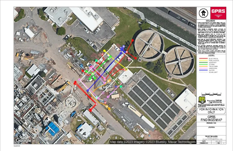
Why Professional Utility Locating Matters
Accurate utility locating helps your team to:
- Avoid costly strikes and delays
- Keep your crew and site safe
- Stay compliant
- Prevent change orders and rework
- Keep your project moving confidently and on schedule
If you share a few details about your site, we can provide a fast, accurate quote for utility locating and mapping services and help you choose the most cost-effective utility loctating solution.
Why Accurate Utility Locating is Essential for Damage Prevention
Utility locating services are significantly less expensive than the cost of striking a utility line.
A white paper published in April 2023 by the Infrastructure Protection Coalition (IPC) highlights major failures in the nation’s damage prevention system used to protect the public and prevent damage to underground utility lines. These failures are responsible for over $30 billion in annual societal and utility line damage costs, and an additional $61 billion in annual waste and excess costs.
The Common Ground Alliance 2024 DIRT Report, the only comprehensive accounting of buried infrastructure damages in North America, found that 9 of the top 10 known root causes of utility damages occur during utility work itself. This means that the very activities intended to install or maintain utilities are often the ones most likely to damage existing buried lines when locating is inaccurate.
It is important for general contractors and engineers to carefully plan and complete work with an accurate utility locate and map. By partnering with GPRS for accurate utility locating, your team can prevent costly outages, injuries, delays, and downtime, protecting your people, your schedule, and your budget.
Do You Need Both Public and Private Utilities Located?
Yes, you do. Both public and private utilities need to be accurately located and mapped to ensure safety, avoid costly repairs, and prevent service outages. Public utility locators (811) mark registered lines up to the meter, while private utility locators can both verify your 811 locates, and find service lines beyond the meter that are often unmapped and dangerously forgotten.
More than 65% of all buried utility lines on any given site are unregistered/private utilities that 811 does not locate.
Private utilities are utilities which extend beyond service meters or public utilities, often on to privately owned property. Examples of private utilities can include electrical feeders and gas mains running through parking lots or to critical facilities such as hospitals or fire stations. They can also include lines running to and from substations, heavy industrial facilities, and refineries. These utilities would be owned and maintained by the property owner, placing them outside of the jurisdiction of public utility locating companies.
GPRS: The Most Accurate Utility Locating Team in the Industry
When you hire GPRS, you’re hiring highly trained SIM-certified specialists with over three times the training and hands on experience required by most providers.
With GPRS as your partner, you gain the field verified data and expert support you need to eliminate guesswork, reduce risk, and keep your project on track. No matter the complexity of your site, we deliver the clarity needed to make safe, informed, compliant decisions, from planning through execution.
Learn more about GPRS Utility Locating services.
What is SIM Certification?
SIM certification is the rigorous training and qualification process GPRS Project Managers undergo in Subsurface Investigation Methodology (SIM), the industry’s most advanced standard for utility locating and subsurface investigation.
SIM is a structured, repeatable process designed to ensure maximum accuracy and safety when locating underground utilities or scanning concrete.

What SIM Certification Involves
To become SIM certified, a GPRS Project Manager must complete:
- 320 hours of mentored field training
- 80 hours of classroom training (hands on and curriculum based)
This far exceeds typical industry recommendations, which call for only 8 hours of classroom work and 60 hours of practice for Level 1 GPR certification.
What SIM Certification Ensures
A SIM certified GPRS Project Manager is trained to:
- Use multiple technologies (GPR + EM locators, and other complementary technologies) to cross verify findings
- Follow a step by step, repeatable process for data collection
- Adhere to a detailed SIM checklist to ensure accuracy in every situation
- Be prepared for unique, real-world scenarios
Why It Matters to Customers
Choosing a SIM certified GPRS Project Manager means you get:
- 99.8% accurate utility locating & mapping
- Reduced risk of utility strikes, delays, and costly rework
- Consistent, repeatable results across every project
- Safety focused, highly trained professionals
GPRS Project Managers have maintained a 99.8% accuracy rate in utility locating since 2017.
Learn more about Subsurface Investigation Methodology (SIM).
Industries GPRS Serves for Utility Locating
Healthcare & Hospitals
If you operate a hospital, clinic, surgical center, nursing home, lab, or pharmaceutical facility, you’re likely renovating, expanding, or adding new equipment regularly. You rely on uninterrupted power, water, and communications, so we locate your underground utilities to help you avoid service outages, reduce risk, and keep patients and staff safe during construction. Learn more about utility locating for Healthcare facilities.
Higher Education & K–12 Schools
Whether you manage a university campus, college, or school district, your facilities frequently undergo retrofits, construction, and infrastructure upgrades. We help you verify and map subsurface utilities, so your projects move forward safely and without unexpected delays. Learn more about utility locating for schools, universities, colleges, and campuses.
Data Centers
If you manage an enterprise, colocation, cloud, hyperscale, edge, or modular data center, you know a single utility strike can cause catastrophic downtime. We provide precise utility locating to protect your critical power and fiber lines during new builds, expansions, and retrofits so uptime stays uninterrupted. Learn more about utilty locating for data centers.
Manufacturing, Industrial & Agricultural Facilities
Plants, factories, and industrial sites constantly update production lines, equipment, and infrastructure. We help you locate underground power feeds, process piping, communications, gas, and water lines so your upgrades and installations stay on schedule and safe. Learn more about utility locating for facilities.
Telecom
Telecom networks depend on extensive underground fiber, conduit, power feeds, and communication lines that must remain active and protected during upgrades and new installations. Whether you're expanding fiber routes, installing 5G infrastructure, or upgrading network capacity, accurate utility locating helps you avoid strikes, prevent service outages, and keep projects on schedule. Learn more about utility locating for the telecom industry.
Oil & Gas
Oil and gas facilities depend on extensive underground infrastructure, including pipelines, flow lines, power feeds, communication cables, and control systems, that must be protected during maintenance, expansions, and new construction. Accurate utility locating helps your team avoid damaging critical lines, prevent shutdowns and environmental incidents, and keep high risk operations running safely and efficiently. Learn more about utility locating for oil and gas facilities.
Transportation & Infrastructure
Airports, railways, transit systems, ports, and DOT projects depend on complex underground networks. We help you map and avoid buried utilities so you can prevent strikes, maintain public safety, and keep major infrastructure projects on time. Learn more about utility locating for transportation and infrastructure.
Power Transmission, Distribution & Generation + Renewable Energy
Whether you're working on transmission lines, distribution networks, substations, power generation facilities, or building solar, wind, or EV charging infrastructure, you need accurate subsurface data to work safely. We locate underground utilities, grounding grids, duct banks, and conduits so you can trench, install foundations, and expand energy systems without risking outages, delays, or costly strikes. Learn more about utility locating for the power industry.
Real Estate Development & Commercial Property Management
Developers, landlords, and CRE teams rely on accurate utility locating to protect investments, speed up development, and reduce liability. Whether you’re doing due diligence, preconstruction planning, or a major redevelopment, we help you understand exactly what’s underground so you can build with confidence.
Public Works & Municipalities
City engineers, public utility districts, parks departments, and municipal campuses depend on accurate utility maps for capital improvement projects. We help you avoid service disruptions and keep critical community operations running smoothly.
Defense & Government Facilities
If you’re managing a military base, federal complex, or secure government site, precision and safety are non-negotiable. We help you locate underground utilities before construction or system upgrades so you can maintain security and avoid outages. Learn more about utility locating for government and defense.
Hospitality & Entertainment
Hotels, stadiums, arenas, theaters, and convention centers renovate frequently, and you rely on continuous power, water, and communications to serve guests and events. We help you avoid outages and protect your operations while work is taking place. Learn more about utility locating for hospitality and entertainment projects.
Historic Preservation & Adaptive Reuse
If you're restoring or converting an older property, you may be dealing with undocumented renovations and abandoned or unknown utilities. We help you safely locate aging electrical, gas, water, and sewer lines so your crews can work without damaging historically significant structures. Learn more about utility locating for historic preservation and adaptive reuse.
Water & Wastewater Treatment Plants
Your facilities contain dense, overlapping piping systems, chemical feeds, high voltage power, and control networks. We give you precise subsurface utility maps that support upgrades, expansions, and emergency repairs, without causing service disruptions. Learn more about utility locating for water and sewer projects.
Environmental Due Diligence
Accurate subsurface data is critical during Phase II environmental assessments. GPRS utility locating identifies underground utilities, UST components, and other subsurface features so you can clear soil borings, install vapor pins, and drill safely without risking damage. Our custom utility CAD maps protect existing infrastructure, while Conceptual Site Models (CSMs) help reveal potential contaminant migration pathways and guide informed next steps in your investigation. Learn more about utility locating for environmental due diligence.
Retail & Restaurants
If you manage retail spaces or restaurants, frequent remodels, kitchen upgrades, or tenant improvements require safe utility avoidance. We help you identify underground water, sewer, grease, gas, and electrical lines so your operations stay open and productive. Learn more about utility locating for retail and restaurants.
Airports & Aviation
From airfields to terminals and hangars, you operate above complicated underground networks, fuel lines, comms, runway lighting, stormwater, and power. We provide the accurate utility locating you need before construction, signage installation, lighting upgrades, or pavement work to prevent interruptions and safety risks. Learn more about utility locating for airports and aviation.
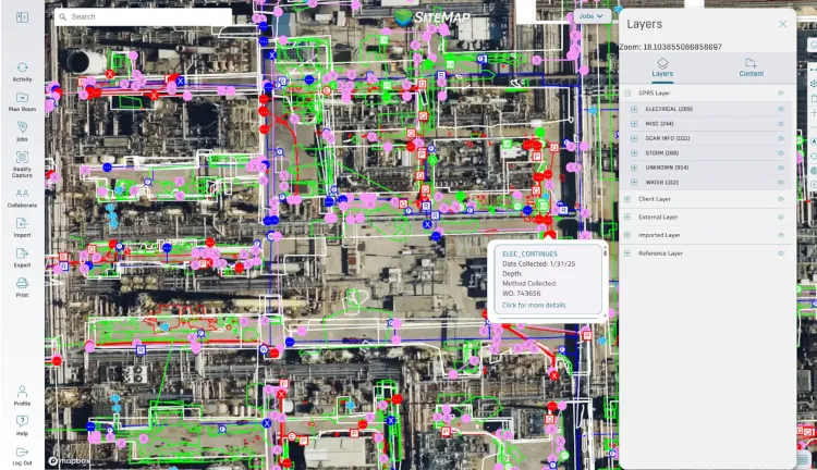
Reasons to Choose GPRS for Utility Locating Services
When you choose GPRS, you’re choosing accuracy, safety, and confidence on every project. From transparent pricing to unmatched SIM certified expertise, our team is committed to delivering detailed utility location field markings and maps that you need to plan, design, dig, and build without unexpected setbacks.
Utility locating is an investment that protects your people, your budget, and your schedule, and with GPRS, you can move forward knowing your site has been mapped with industry leading precision.
GPRS is the nation’s leading above and below-ground existing conditions visualization company, delivering unmatched utility locating accuracy through advanced technology and SIM-certified Project Managers to help our clients Visualize the Built World®.
Contact GPRS for utility locating pricing, and let us help you complete your project safely, efficiently, and with total confidence.
GPRS Pinpoints Source of Slip Hazard at California Elementary School
GPRS utilized leak detection and utility locating equipment to help uncover the hidden source of a hazardous leak at an elementary school in California.
Thornhill Elementary School in Oakland, California has been in operation since 1958 and currently services approximately 400 students.
To keep pickups and drop offs organized, they have a designated area for that near the school’s entrance, so students and parents know where to go at the beginning and end of the school day. Administrators had noticed water surfacing in that area.
While no student had slipped or fallen, school officials didn’t want the problem to persist until someone did.
And algae had begun to grow in it as well, so they needed to address the issue quickly.
The school tasked GPRS Leak Detection Project Manager William Walhovd with locating the source of the leak before any kids were harmed.
Walhovd arrived at the school thirty minutes before the students arrived. However, students began showing up before he could identify the leak.
Thanks to his previous working relationship with the client, Walhovd was able to continue the job without affecting the school day.
“I've done a lot of work with that school district in the past,” Walhovd explained. “We usually try to get there as early as we can, but those guys are pretty good. They show up and have things ready for me before I get there because we try to get in and get out really quick.”
Walhovd began the leak detection process by listening for the leak with an acoustic leak detector.
“Usually when the water's surfacing, I try to listen to the surface where the water's coming out because usually, I can hear something,” Walhovd explained. “In this case, it was a pretty wide area and it wasn't making very much noise.”
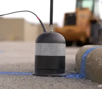
Since our Leak Detection Project Managers are also expertly trained in utility locating, Walhovd shifted gears to ensure he could pinpoint the leak.
“Then, we switched over to locating the pipes that may potentially run through there,” Walhovd explained. “So, we connected to a bunch of different water lines until that one showed up. We marked the location of it. We knew exactly where it was running through, and we knew what lines it connected to.”
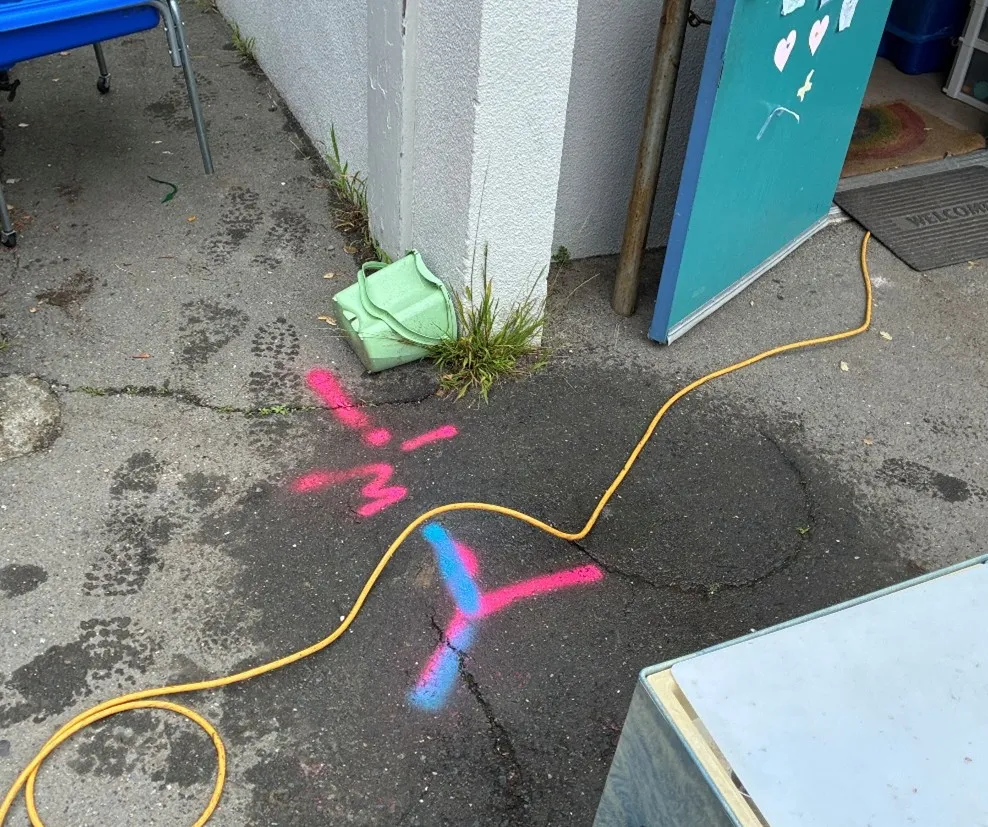
GPRS Project Managers utilize electromagnetic (EM) locators and ground penetrating radar (GPR) to locate utilities. The way these devices collect data is complementary to the other, allowing for the most accurate results.
New layers added over the years made the asphalt above the water lines very thick. Because of this, the signal was still faint.
However, Walhovd had one more trick up his sleeve to ensure he could listen to the pipes and locate the leak.
“Since we still couldn’t hear the pipes through the asphalt, we drilled some holes so that we could listen closer,” Walhovd explained. “I put a probe in the ground to allow the sound to reach my microphone better.”
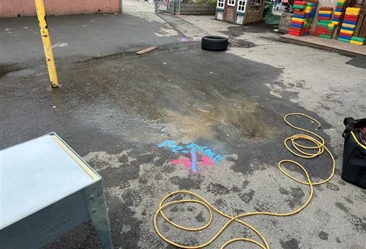
Upon further investigation, Walhovd discovered a previously unknown buried water valve that controlled the leaking pipe.
Without GPRS’ 99.8% accurate utility scans and pinpoint leak detection services, that valve would have stayed lost and the leak would have continued, putting more students, teachers, and parents at risk.
Walhovd shared his findings with the client via SiteMap® (patent pending), GPRS’ cloud-based infrastructure management platform that shows your above and below ground infrastructure in one place.
From skyscrapers to sewer lines, GPRS Visualizes YOUR Built World® to keep your projects on time, on budget, and safe.
What can we help you visualize?
FREQUENTLY ASKED QUESTIONS
What is an annual leak survey and why do they matter?
An annual leak survey is a scheduled inspection of water infrastructure to identify and document leaks. These surveys are critical for regulatory compliance, environmental protection, and cost control. Regular assessments reduce water loss, prevent hazardous conditions, and extend asset life. For municipalities and facilities, annual surveys support proactive maintenance and budget forecasting.
How long does a leak detection usually take?
How long it takes to find your leak depends on the system size, complexity, and access conditions. A standard survey of a small facility or municipal segment may take several hours, while larger networks can require multiple days. GPRS optimizes efficiency through pre-survey planning and site walks, real-time data collection, and advanced equipment, minimizing disruption and ensuring timely reporting.
Can GPRS determine the size of a detected leak?
GPRS determines the size of the leak by how far the leak signal travels between contact points and the pitch of the tone received. GPRS does not, however, produce formal leak estimations.
What is SIM?
Subsurface Investigation Methodology (SIM) is a standard operating procedure and set of professional specifications that work as a guide for utility locating experts when scanning for buried utility lines. All GPRS Project Managers are required to achieve SIM 101 certification, which requires 80 hours of hands-on training in a classroom setting and 320 hours of mentorship in the field. For reference, the American Society for Nondestructive Testing’s (ASNT) minimum training recommendation includes eight hours for training and 60 hours practicing GPR to achieve NDT Level 1 certification in ground penetrating radar (GPR) scanning.
SIM requires the use of multiple, complementary technologies, like GPR scanning and electromagnetic (EM) locating, when locating buried utilities or scanning a concrete slab.
GPRS Helps Keep Workers & Patrons Safe by Pinpointing Leak in Ski Resort’s Snow Melting System
GPRS combined gas testing practices with pinpoint leak detection equipment to locate a leak at a ski resort in Olympic Valley, California.
Palisades Tahoe is recognized as one of the top ski resorts in the country and played host to the 1960 Winter Olympics.
Like most resorts, Palisades utilizes snow-melting systems in high traffic areas, like stairs, decks, and walkways, to maintain a safe environment for skiers and workers. The snow-melting systems produce radiant heat through a boiler loop in the ground.
So, when resort facilities management noticed a dip in their glycol levels - the amount of ethylene or propylene glycol that mixes with water for efficient heat transfer - they suspected trouble. Once the system failed a pressure test, they were certain they had a leak.
GPRS Leak Detection Project Manager William Walhovd was tasked with locating the source of the leak.
Walhovd began his search for the leak in the boiler room and used electromagnetic (EM) locators to locate where the boiler loop connects to the staircase.
“We started by connecting onto the copper piping at the boiler,” Walhovd explained. “It got us most of the way to the staircase and then the signal kind of died off, so we figured there was a transition from copper into another material. But we had that all marked out.”
EM locators are traditionally used by GPRS Project Managers to locate utilities with ground penetrating radar (GPR) used as a complementary technology along with it. However, utility locating practices help with leak detection by showing the location of subsurface infrastructure, so they know where to listen.
The next stage involved the use of a thermal imaging camera to gain a better understanding of the piping in the staircase. With this information at his disposal, Walhovd began listening for leaks along the surface using an acoustic leak detector.
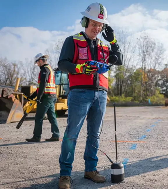
Acoustic leak detectors locate leaks with a sensitive ground microphone or an acoustic listening device. GPRS Leak Detection Project Managers use headphones to listen for and isolate the leak tone. When used at the surface level, a bell-shaped acoustic shield referred to as an “elephant’s foot” can be added to the ground microphone to help isolate the sounds coming from the pipes.
After listening to the pipes in the staircase, Walhovd couldn’t hear anything that resembled a leak. So, he changed gears by applying gas tracing methods.
“When I didn't hear anything in the pipes along the stairs, we drained the system and applied a non-flammable, non-toxic gas mixture to essentially turn it into a gas leak,” Walhovd explained. “While listening in that area, we could hear the gas escaping.”
When asked what the difference was between the sound of a leaking pressurized water pipe with and without gas tracing, Walhovd explained the following:
“It's very different. If you can hear like the water running in your house if somebody uses the shower. That's what water leaks sound like. And [gas tracing a water leak] sounds like somebody blowing bubbles underwater. You'd hear water and gas escaping at the same time, but it's a totally different sound.”
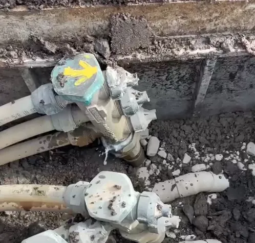
Upon further investigation, Walhovd found the source of the leak.
“We discovered that there was a box that was buried and the lid of the box was crushed,” Walhovd explained. “As soon as we opened it up, we could see that the manifold inside was up against the vault lid that was crushed and that was leaking. The vault lid was in rough shape and the client suspected that recent crane usage in the area was to blame for the leak.”
The client fixed the leak on the spot by using a pair of pliers to tighten the vault lid and hasn’t had any problems since.
From skyscrapers to sewer lines, GPRS Visualizes the Built World to keep your projects on time, on budget, and safe.
What can we help you visualize?
FREQUENTLY ASKED QUESTIONS
What is an annual leak survey and why do they matter?
An annual leak survey is a scheduled inspection of water infrastructure to identify and document leaks. These surveys are critical for regulatory compliance, environmental protection, and cost control. Regular assessments reduce water loss, prevent hazardous conditions, and extend asset life. For municipalities and facilities, annual surveys support proactive maintenance and budget forecasting.
How long does a leak detection usually take?
How long it takes to find your leak depends on the system size, complexity, and access conditions. A standard survey of a small facility or municipal segment may take several hours, while larger networks can require multiple days. GPRS optimizes efficiency through pre-survey planning and site walks, real-time data collection, and advanced equipment, minimizing disruption and ensuring timely reporting.
Can GPRS determine the size of a detected leak?
GPRS determines the size of the leak by how far the leak signal travels between contact points and the pitch of the tone received. GPRS does not, however, produce formal leak estimations.
What is SIM?
Subsurface Investigation Methodology (SIM) is a standard operating procedure and set of professional specifications that work as a guide for utility locating experts when scanning for buried utility lines. All GPRS Project Managers are required to achieve SIM 101 certification, which requires 80 hours of hands-on training in a classroom setting and 320 hours of mentorship in the field. For reference, the American Society for Nondestructive Testing’s (ASNT) minimum training recommendation includes eight hours for training and 60 hours practicing GPR to achieve NDT Level 1 certification in ground penetrating radar (GPR) scanning.
SIM requires the use of multiple, complementary technologies, like GPR scanning and electromagnetic (EM) locating, when locating buried utilities or scanning a concrete slab.
Risk Management Across Upstream, Midstream, and Downstream Projects
Risk Management in the Oil & Gas Industry
Oil and gas projects operate in highly intricate environments. From pipelines to refineries, every phase carries unique challenges. Whether the work is happening along a pipeline corridor, at a terminal, or inside a refinery, you need clear, accurate site information to plan safely and keep work moving.
Outdated or missing records can lead to big problems quickly. When information is scattered across teams, issues like design conflicts, utility strikes, delays, budget overruns, and risks for workers and nearby communities can arise.
That matters even more when you consider the size of the industry.
According to the Environmental Protection Agency (EPA), “The oil and gas sector is the largest energy producer in the U.S., responsible for about 74% of primary energy production.”
When all stakeholders can work from the same up-to-date, digitized information, your team can:
- Reduce risk
- Stay coordinated
- Move projects forward with confidence
This applies across upstream, midstream, and downstream operations.
What Are the Oil & Gas Industry Segments?
The oil and gas industry has three main segments: upstream, midstream, and downstream. Together, these segments form the hydrocarbon value chain. This process begins with finding and producing resources. Next, it involves transportation and storage. Finally, it ends with refining and distribution. Large integrated companies might join all three areas, and other companies often focus on just one segment. Their choice depends on their assets, expertise, and market goals.
Upstream
The upstream segment focuses on finding and producing oil and natural gas. This segment includes exploration, drilling, field development, and production. In practical terms, this is the front end of the industry. Operators identify hydrocarbon reserves, drill wells, and complete them. They also bring crude oil and natural gas to the surface for initial handling and transfer.
This segment has some of the industry’s highest technical and financial risk, because no operator can fully predict the outcome of a well before drilling starts. The key uncertainties include:
- Reserves
- Reservoir quality
- Expected production
- Commodity prices
Upstream work requires capital, technical precision, and disciplined risk management. In 2025, upstream activity in the United States hit a record high. Crude oil production averaged 13.6 million barrels per day, based on the EIA data. That new annual record shows how central exploration and production remain to the domestic energy supply.
Midstream
The midstream segment connects upstream and downstream. This segment deals with gathering, transporting, storing, and transferring crude oil, natural gas, and natural gas liquids (NGL). Midstream relies on a broad network of infrastructure and logistics systems.
Thomson Reuters Practical Law states that “Oil and NGLs may be transported by ship, rail, pipelines, and truck. Because gas takes up a lot of space, it is primarily transported via pipelines or in specially designed vessels in the form of liquefied natural gas.”
However, pipeline construction requires a significant upfront investment because midstream infrastructure operates at an enormous scale. For example, the Pipeline and Hazardous Materials Safety Administration (PHMSA) oversees more than 3.4 million miles of pipelines. These systems transfer almost all the natural gas used in the U.S. and about two-thirds of hazardous liquid petroleum products.
Downstream
The downstream segment converts raw hydrocarbons into finished, usable products. This segment includes:
- Refining
- Processing
- Blending
- Marketing
- Distribution
These assets make the segment closest to commercial and consumer demand. Refineries and processing facilities turn crude oil and natural gas into products such as gasoline, diesel, jet fuel, lubricants, asphalt, petrochemical feedstocks, and pipeline-quality gas.
Downstream operations require reliable, high-value equipment across refineries, processing plants, and storage facilities. industrial systems. Refining processes include major units such as:
- Atmospheric distillation
- Catalytic cracking
- Catalytic reforming
- Hydrocracking
- Hydrotreating
All these units separate, upgrade, and treat hydrocarbons into marketable products. These products include fuel retail, wholesale distribution, chemical sales, and aviation fuel.
How the Oil & Gas Segments Work Together
These three segments operate as a continuous system rather than as isolated silos. Upstream gathers raw hydrocarbons. Midstream transports and stores them. Downstream turns the hydrocarbons into finished products and delivers them to the market. Each segment performs a distinct function, but none can operate effectively without the others.
That structure also explains why the oil and gas industry relies on such a wide range of disciplines. These include geology, drilling, engineering, logistics, processing, refining, integrity management, and large-scale infrastructure operations.
What is the Oil & Gas Industry Outlook?
Oil and gas companies enter 2026 with a more selective growth mindset. Deloitte's 2026 Oil and Gas Industry Outlook expects operators to balance policy-driven opportunities against weaker macro conditions, lower oil prices, and continued pressure on margins. That means many companies will stick to capital discipline. This will happen even as supportive U.S. policies create new chances for drilling, expanding acreage, and developing infrastructure.
U.S. natural gas and liquefied natural gas (LNG) companies plan to boost spending and grow their shale positions. This comes as demand for liquefied natural gas (LNG) rises and data centers increase their power needs.
These trends support a strong future for natural gas. Oil producers, on the other hand, are more likely to hold off on increasing investment. They prefer to see a clearer improvement in global supply and demand first.

Deloitte also reports that nearly “70% of the U.S. oil and gas companies it analyzed plan to restructure portfolios, optimize costs, or divest noncore assets, while many continue directing a large share of cash flow to dividends and buybacks.”
In other words, the industry outlook predicts targeted growth, capital discipline, and higher-return assets over broad-based expansion.
Cost Pressures
Cost pressure remains one of the clearest constraints on industry growth. Deloitte highlights 10% to 25% tariff actions on crude feedstocks, steel, and aluminum that don't comply with the United States-Mexico-Canada Agreement (USMCA). This agreement highlights that equipment like compressors and pumps are major cost drivers that could reshape the sector’s economics.
Oil and gas operators depend on materials and equipment from around the world. So, even small changes in trade policy can raise procurement costs for upstream, midstream, and downstream projects.
Deloitte estimates that “The announced US tariffs on these components and key input materials, including steel, aluminum, and copper, could increase material and service costs across the value chain by 4% to 40%, potentially compressing industry margins.”
As a result, many companies will likely change their procurement strategies to decrease volatility exposure. As documented in Deloitte industry outlook, this could involve operators to:
- Diversify suppliers
- Depend more on domestic or non-tariffed sourcing
- Boost local fabrication when possible
- Update contracts to share cost escalation risks with EPC firms and vendors
Scaling LNG
LNG remains one of the strongest growth drivers in the oil and gas outlook. The IEA expects global natural gas demand growth to accelerate in 2026 after slowing to less than 1% in 2025. The agency also expects global LNG supply growth to exceed 7% in 2026, marking the fastest pace of expansion since 2019.
North America will lead much of that expansion.
“North America is set to account for the vast majority of the 40 bcm increase,” per the IEA.
Investment activity also remains strong. In 2025, over 90 bcm per year of liquefaction capacity reached a final investment decision. This decision was marked the second-highest annual total ever recorded, with the United States accounting for more than 80 bcm of approved annual capacity.
Digital Transformation
Digital transformation is shifting from experimentation to scaled deployment.
According to Oleg Fonarov, CEO of Program-Ace, and author of Forbes' Trends In Digital Transformation In The Oil & Gas Industries, “relying on outdated methods entails higher costs, unexpected failures and unnecessary risks.”
Fonarov also states that “…using digital tools isn’t just about keeping up with trends. It’s a way to work smarter, cut unnecessary costs and create a safer, more efficient environment for everyone in the industry.”
More oil and gas companies are expected to move beyond isolated pilots and push advanced technologies, especially:
- Real-time analytics
- Cloud platforms
- Internet of Things (IoT)-enabled sensors
- Digital twins
- Artificial intelligence (AI) and machine learning (ML)
.webp)
Energy, Oil, & Gas Magazine notes that “automated workflows reduce human error and boost safety.”
Upstream operators use advanced seismic imaging and AI to improve drilling accuracy. Downstream refineries rely on predictive analytics to fix maintenance issues before they turn into costly disruptions.
How Does the Oil & Gas Industry Leverage Digital Twins?
The oil and gas industry uses digital twins to create dynamic virtual representations of physical assets and systems. Operators update these models with real-time operational data, historical information, and advanced analytics.
IBM explains that this approach helps operators:
- Predict future behavior
- Improve operational efficiency
- Gain deeper insight into critical asset performance in the field
IBM states that, “one of the most beneficial applications of digital twins in the oil and gas industry is predictive maintenance (PdM).”
As mentioned previously, operators can spot maintenance needs sooner. This way, they can reduce unplanned downtime and find potential failures before they occur. Digital twins also support improvements in efficiency, safety, and asset optimization. They help improve operations across upstream, midstream, and downstream.
How Can GPRS Support Oil & Gas Projects?
GPRS supports oil and gas projects across the country, from pipeline corridors to refinery facilities, delivering comprehensive site visualization both above and below-ground.
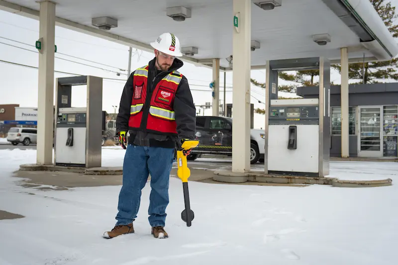
GPRS’ Services Include:
1. Utility Locating:
- Identifies, marks, and maps underground infrastructure such as pipelines, tanks, and additional buried utility lines
- Supports safer work across upstream fields, midstream corridors, and downstream facilities
- Reduces the risk of utility strikes, environmental accidents, and costly project delays
- Learn more about GPRS’ Utility Locating Services
2. Concrete Scanning:
- Identifies rebar, conduits, and post tension cables before coring, cutting, or drilling
- Protects slabs, well pads, and structures during refinery upgrades and plant modifications
- Reduces risk during tie-ins, anchoring, crane setup, and shutdowns
- Learn more about GPRS’ Concrete Scanning Services
3. 3D Laser Scanning:
- Saves time, money, and headache compared to manual measurement methods
- Captures 2-6mm accurate, real-world documentation of refineries, offshore platforms, and pipelines
- Improves coordination by giving architects, contractors, and engineers a shared view of as-built site conditions
- Learn more about GPRS’ 3D Laser Scanning Services
4. Video Pipe Inspection:
- Inspects water, sewer, and lateral pipelines using a robotic crawler, lateral launch, and push cameras
- Helps locate clogs, cross bores, structural faults, and pipe damage before maintenance, repairs, or tie-ins
- Delivers NASSCO-certified WinCan reports with the exact location, video, photo, and severity for each defect
- Learn more about GPRS’ Video Pipe Inspection Services
5. Leak Detection:
- Non-destructive method to pinpoint hidden leaks in water distribution and/or fire suppression systems
- Helps reduce downtime, repair costs, and system loss in active plants, terminals, and refineries
- Enables you to address leaks early to avoid damage to the surrounding ground and structures
- Learn more about GPRS’ Leak Detection Services
SiteMap®
- Stores all your utility maps, KMZ files, CADD/BIM deliverables, and virtual tours for instant access
- User-friendly and customizable GIS platform
- Break down information silos to enhance safety, reduce costs, and plan with confidence
- Learn more about GPRS' infrastructure visualization platform, SiteMap
GPRS utilizes a “boots on the ground” approach and deploys Subsurface Investigation Methodology (SIM)-Certified Project Managers across the country to provide in-person field services.
Case Study: GPRS Utility Locate and 3D Laser Scan for a Gas Station
A gas station needed precise utility locating and as-built documentation to support planned site upgrades and strengthen emergency response planning for potential leaks. GPRS delivered 2D utility maps, a 3D BIM model, and a conceptual site model (CSM) documenting the gas station, underground storage tank (UST) system, and surrounding infrastructure. Read the full case study.
.webp)
Problem
- The gas station lacked reliable as-built site data needed for environmental compliance, upgrade planning, and emergency response
- The client did not have an accurate CSM to understand the likely contaminant fate and transport in the subsurface
Solution
- GPRS Project Managers performed utility locating, video pipe inspection, leak detection, 3D laser scanning, and drone photogrammetry to document existing structural and subsurface conditions
- The CADD/BIM Team delivered data in point cloud, 2D maps, and 3D BIM formats to improve planning, reduce uncertainty, and help the client avoid dangerous mistakes
- The deliverables gave the client accurate site data to support drilling, leak assessment, and upgrade planning
Benefits
- Infrastructure locating and mapping supports safer subsurface work, including soil borings and concrete coring for vapor pins, by reducing clashes and utility strikes
- Accurate as-built maps and models help teams avoid damaging USTs, system components, and buried utilities during investigation and sampling
- Site data stored in GPRS' SiteMap supports stakeholder access, leak response planning, CSM development, and more-informed remediation decisions
Accurate structural and subsurface information helps you reduce risk, improve coordination, and make informed decisions in complex project environments. GPRS provides field-verified data and full-site visualization to support safer planning, streamlined communication, and more efficient execution across upstream, midstream, and downstream work.
Let us help you digitize your oil and gas operations. What can we help you visualize?
Frequently Asked Questions
What is utility locating?
Utility locating is the process of identifying, marking, and mapping buried private and/or public utilities before excavation, drilling, or coring begins. Utility locating helps contractors avoid utility strikes, reduce clashes, and verify existing site conditions. GPRS can locate private and public utilities and provide digital utility maps with depth information for oil and gas projects nationwide. Learn more about GPRS’ Utility Locating Services here.
What is 3D laser scanning?
3D laser scanning is a reality capture method that records accurate existing site conditions that is then processed into one cohesive point cloud. General contractors use this method to document architectural, structural, and MEP systems for planning, clash detection, and facility modifications. GPRS’ CADD/BIM Team can turn that scan data into 2D CAD drawings, 3D BIM models, 3D mesh models, and virtual tours for easier field, design, and office coordination. For example, GPRS used 3D laser scanning for a midstream energy project to capture flange data for gas processing and transportation components so the client could speed up prefabrication and reduce field changes in this case study: 3D Laser Scans Gas Processing and Transportation Components.
What is the difference between BIM models and digital twins?
A BIM model is a detailed, static, digital model used mainly for design and construction, while a digital twin adds live data to show how an asset performs over time. BIM is most valuable during planning and building, and digital twins are most valuable during operations and maintenance. GPRS delivers 3D BIM models, which can serve as the building blocks to your digital twins. Learn more about the difference between 3D BIM models and digital twins here.
How does GPRS create a conceptual site model (CSM)?
GPRS creates the utility portion of a conceptual site model by collecting accurate field data on buried infrastructure and existing site conditions. That data can identify likely liquid migration pathways and potential voids where soil vapor could introduce additional hazards. SiteMap can then store a CSM and geolocated, layered utility data so stakeholders can quickly access and share current site records.
Risk Mitigation for EV Charging Installation and Management
Privately owned and publicly operated EV charging stations continue to populate nationwide. Whether they are commercial EV charging stations owned by businesses or public charging stations owned by local governments, EV charging adoption is growing rapidly.
In 2016, there were 44,354 EV charging ports and 17,810 charging stations in the United States according to the U.S. Department of Energy.
As of March 2026, that number has more than quadrupled as there are over 270,000 charging ports and over 80,000 charging stations.
The Department of Energy claims the U.S. will need 28 million EV charging ports by 2030, growing the current infrastructure by a multiple of ten in only a few years.
Despite the exponential growth in EV infrastructure, there are rising concerns among EV drivers, installers, and managers.
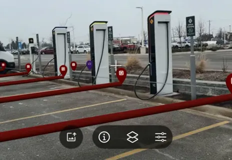
What is the EV Charging Delivery Landscape?
Rising Demand for EV Charging Infrastructure
The usage of public EV charging ports reached an estimated 141 million sessions in 2025, which marked a 30% increase year-over-year.
The increase in EV adoption indicates a higher demand for EV charging infrastructure. However, in 2025, charging sessions increased by 34% while new charging ports only grew by 16%, according to a ChargePoint report.
Nationwide efforts are taking shape as federal programs develop a national EV charging infrastructure network.
The U.S. Department of Transportation (DOT) enacted the National Electric Vehicle Infrastructure (NEVI) Formula Program in 2021, where they allocated $5 billion for states to “strategically deploy electric vehicle (EV) chargers and to establish an interconnected network to facilitate data collection, access, and reliability.”
As the nation needs more charging stations at an increasingly faster pace, projects will require tighter timelines and higher reliability expectations to meet the demand.
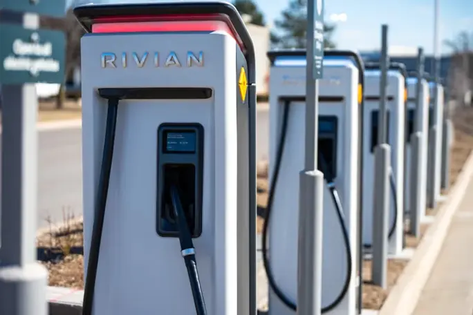
Permitting Process
The installation of EV charging stations involves extensive permit requests.
Before installing anything, property managers must obtain the proper permits to avoid citations, fines, business closures, and public endangerment from improper practices.
There are different permits for residential and commercial projects. Account to workflow specialists, PermitFlow, the permitting process can take 1-4 weeks for residential projects and 4 weeks to multiple months for commercial, as it depends on the scope of work.
The permitting process for commercial buildings includes:
- Site assessments conducted by a qualified electrical contractor that assesses the electrical capacity and layout of the property
- Submitting detailed site plans like electrical schematics and load calculations to local government agencies
- Inspections that ensure the EV station meets building codes
Commercial EV’s Intricate Construction Process
Once officials approve the permits, the installation process can begin.
Installing EV charging stations involves:
- Upgrades as needed to the existing electrical systems
- Running electrical conduit
- Installing protective bollards
- Mounting the chargers to walls or support structures
- Connecting the unit to the site’s electrical panel.
The process can take weeks to years, according to industry advocates like the Center for Sustainable Energy, depending on the scope of the job and how extensive the necessary upgrades are.
Cutting concrete, trenching, and directional boring is usually required for installation. Any time a project involves breaking ground, there is the possibility of striking utilities or other subsurface obstructions, especially if the utility information is outdated. According to Construction Dive, damage to buried utilities imposes more than $61 billion per year in waste and excess costs on communities.
Without accurate utility data, the chances of striking a utility line are very high, which can lead to massive delays, high repair costs, and potentially fatal injuries for workers.
Insufficient Grid Capacity Poses Risk
One of the biggest obstacles when installing EV chargers is the lack of grid capacity.
Many locations lack the electrical capacity needed to support EV charging stations. Because of this and the exponential rise in EV demand, building managers have no choice but to implement upgrades to electrical panels, transformers, and/or utilities to avoid missing out on the business of EV drivers. These upgrades are also very expensive and often slow to install.
The massive expansion of EV infrastructure is also affecting citywide grid systems. Uncontrolled charging during peak hours, like mornings and evenings, can strain electricity systems, leading to reliability issues.
However, there are initiatives in place like grid modernization efforts and the implementation of smart grid technologies to increase electrical capacity and use AI-based forecasting to monitor energy usage.
Mitigating for Unreliable EV Charging Performance
There is a rising concern among EV drivers regarding the reliability of public EV chargers. A recent study conducted by Harvard Business School analyzed 1 million EV charging customer reviews across North America, Europe, and Asia.
In the study, drivers mentioned coming across broken or malfunctioning equipment often. In the U.S. specifically, drivers claimed that charging stations were less reliable than gas stations, having an average of one in five chargers not working properly.
One way that the U.S. is combating the unreliability label placed on EV chargers is through a three-pronged approach stated by the Federal Highway Administration (FHWA) in February of 2023. They planned to address the issue by:
- Increasing the technical skills and qualifications required for electrical technicians working on Electric Vehicle Supply Equipment (EVSE)
- Requiring a charging station to be fully functional, connected, and available to recharge a driver’s vehicle at least 97% of the time
- Requiring the data for error codes and the duration of an outage during any unsuccessful charging sessions
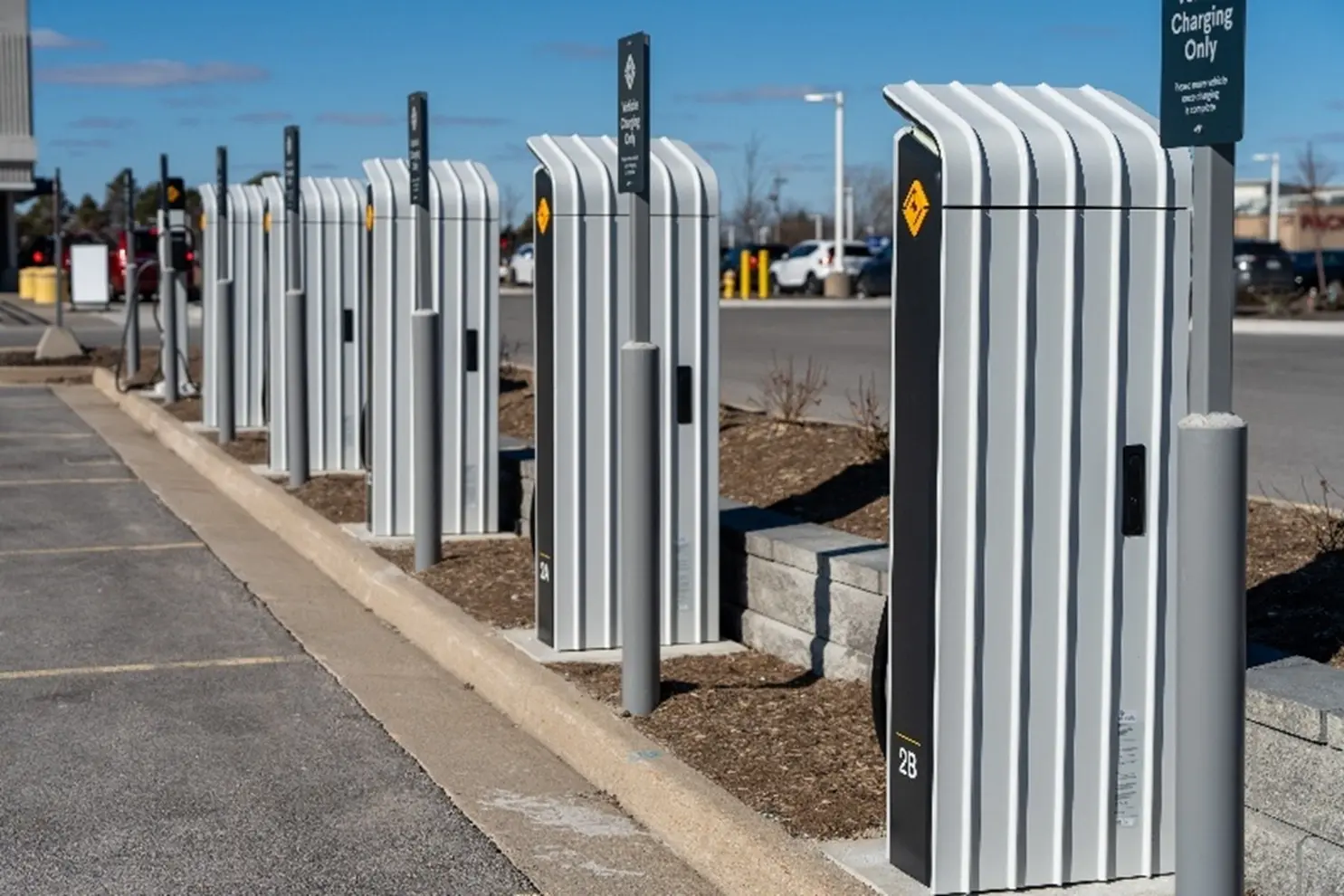
How Can GPRS Support EV Infrastructure Projects?
GPRS offers a wide range of visualization services that make us a trusted resource in AEC industries.
The services GPRS Project Managers execute on job sites include utility locating, concrete scanning, reality capture, video pipe inspection, leak detection, and facility management via SiteMap® (patent pending).
Striking underground utilities near EV charging sites can cause delays, outages, and severe safety risks. GPRS Project Managers maintain 99.8% accuracy on underground utility scans, using complementary technologies like GPR and EM locators to precisely identify public and private utilities. This level of accuracy helps EV projects avoid strikes and stay on schedule.
Damaging a post tension cable can cost up to $30,000 to repair and lead to structural failure. GPRS concrete scanning provides 99.8% accuracy when locating post tension cables, rebar, and conduit. The Green Box Guarantee® confirms areas are clear of obstructions, allowing installers to cut confidently.
Inaccurate as builts create major project risks. GPRS uses LiDAR based 3D laser scanners to produce millimeter accurate point clouds that our in-house Mapping & Modeling team can convert into 2D or 3D deliverables. Reality capture also supports utility locating and concrete scanning by documenting marked out sites and creating models of the subsurface infrastructure. Accurate as-builts reduce miscommunications and rework for EV charging projects.
Cross bores can cause backups, pipe damage, and even explosions. NASSCO certified GPRS Project Managers use CCTV equipment to identify cross bores, along with pipe cracks and defects. All findings are communicated through NASSCO-compliant WinCan reports that help prevent new cross bores from forming during EV power line installations.
Cooling systems for high power chargers must avoid leaks to prevent system failures and fire hazards. GPRS pinpoints leaks by using advanced acoustic equipment and offer routine water loss surveys to maintain system efficiency.
All the data collected from GPRS’ core services are also delivered to our clients via SiteMap, our cloud-based infrastructure management platform. With SiteMap, clients can securely access all their subsurface utility data 24/7. And depending on the access level, clients can share valuable information with their teams and shareholders to make sure everyone is properly informed.
Since 2025, GPRS has added additional layers to the platform to enhance the user experience and house more valuable data. Those additional layers include:
- Sewer Layer: a single source of truth for wastewater and storm assets that include RTK geolocation accuracy and maps with full WinCan reports and in app video for each pipe segment
- Reality Capture Layer: securely stores all point clouds, virtual walkthroughs, and Revit models geospatially all in one place
- Augmented Reality: allows clients to walk their jobsite or facility and see their subsurface utilities in their physical space through the SIteMap Mobile App
How Does GPRS Assist with the Project Lifecycle of EV Installations?
Pre Construction Planning
Highly accurate subsurface utility maps and as builts help eliminate risk when planning any excavations or renovations.
Design Process
LiDAR based 3D laser scanners produce millimeter-accurate 2D and 3D models of sites to help ensure projects progress on time and safely.
Construction
Utility and concrete scanning results provide the information needed to avoid utilities, rebar, post tension cables, and conduit when installing chargers or renovating existing infrastructure.
Post-Construction
All utility, sewer, and reality capture data is at the client’s fingertips 24/7 via SiteMap for them to access and reference during any future projects on site.
CASE STUDY: GPRS Utility Locating Ensures Safety of Ohio EV Charger Installation
The 99.8% underground utility scans conducted by GPRS ensured the safe installation of electric vehicle chargers at an Ohio service station.
Problem
- An EV charging station installer was hired to install chargers at a service station in Cambridge, Ohio
- There were no accurate as-builts of the buried infrastructure on the site
- The installation needed to be completed with minimal disruption to the station’s operations
Solution
- GPRS utilized electromagnetic (EM) locating and ground penetrating radar (GPR) to locate and map the utilities on-site
- The accurate, actionable data was uploaded to SiteMap® (patent pending), GPRS’ infrastructure mapping, and construction and facilities project management software application
- The GPRS Project Manager conducted their investigation without disrupting the service station’s operations
Benefits
- The installers were able to complete their work without striking any buried utilities, ensuring the safety of everyone on-site and the success of the project
- Services at the station were able to continue without the disruptions that would have occurred due to destructive and expensive potholing
- SiteMap ensured the entire project team had 24/7, secure access to the information they needed to avoid costly and potentially dangerous mistakes
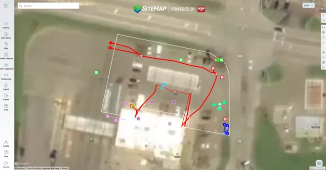
Let us help power your projects with accurate, actionable data as you continue to power the future.
What can we help you visualize?
FREQUENTLY ASKED QUESTIONS
What GPRS deliverables come with EV charging projects?
Some deliverables clients can expect to receive when working with GPRS on EV charging infrastructure projects are:
- High-resolution utility as-builts (PDF or KMZ files)
- Above and below-ground facility and infrastructure mapping
- Conceptual site models (CSM)
- Concrete markings and mapping
- 2D CADD drawings
- 3D models
- Virtual walkthroughs
- As-built creation and existing conditions documentation
- NASSCO-compliant WinCan reports
- Routine water loss surveys
How do contractors and subcontractors utilize SiteMap?
Contractors use SiteMap to access information directly on the job site. They can view utility locations, reports, and drawings on a tablet or laptop.
Example: Before digging, a contractor can open SiteMap to check where utilities are located. They can also use My Dig Board in SiteMap to draw layouts, mark dig zones, plan access routes, and update plans so everyone knows exactly where to excavate.
Having this information in the field saves time and keeps workers safe.
With the role-based access, Subcontractors can use SiteMap to see only the information they need for their jobs. This helps them understand where utilities and structures are located without confusion.
Example: A subcontractor installing electrical lines can look at SiteMap to see nearby utilities and avoid conflicts with other trades.
How does the SiteMap Augmented Reality feature work onsite?
The Augmented Reality feature shows your subsurface utilities in real space with 99.8% accuracy on your phone or tablet. It can only be accessed through the mobile app.
The convenience of viewing your utilities in a physical space allows for enhanced clarity during site walks and reduces risk while digging.
What is SIM?
Subsurface Investigation Methodology (SIM) is a standard operating procedure and set of professional specifications that work as a guide for utility locating experts when scanning for buried utility lines. All GPRS Project Managers are required to achieve SIM 101 certification, which requires 80 hours of hands-on training in a classroom setting and 320 hours of mentorship in the field. For reference, the American Society for Nondestructive Testing’s (ASNT) minimum training recommendation includes eight hours for training and 60 hours practicing GPR to achieve NDT Level 1 certification in ground penetrating radar (GPR) scanning.
SIM requires the use of multiple, complementary technologies, like GPR scanning and electromagnetic (EM) locating, when locating buried utilities or scanning a concrete slab.
Guide to Environmental Due Diligence
Environmental Due Diligence: Phase I & Phase II ESA Guide
What is Environmental Due Diligence?
Environmental due diligence evaluates a property’s environmental conditions and risks. Buyers, lenders, developers, and attorneys request on site reviews to understand potential liabilities, like contamination or hazardous materials, before they purchase, occupy, refinance, or use a property as loan collateral.
When is Environmental Due Diligence Required?
Environmental due diligence is often required before a real estate transaction and is also used for refinancing or construction loans. Commercial lenders and real estate professionals receive a full risk report on a property to understand its potential benefits, downsides, and environmental concerns that may affect value or liability.
What is the Purpose and Process of Environmental Due Diligence?
Environmental due diligence is a key part of any commercial real estate deal because it helps buyers and lenders understand whether a property has any environmental issues that could impact health, safety, or value.
The process typically starts with a Phase I Environmental Site Assessment (ESA), which reviews the site’s history and current conditions to identify any potential problems. If the Phase I ESA raises concerns, a Phase II ESA may follow, involving soil, groundwater, or air sampling to confirm whether contamination is present.
What is a Phase I Environmental Site Assessment?
A Phase I Environmental Site Assessment or Phase I ESA is completed to research the current and historical uses of a property as part of a commercial real estate transaction.
The intent of the assessment is to identify if current or historical property uses have impacted the soil or groundwater beneath the property and could pose a threat to the environment and human health. If these issues are found, it presents potential liability for the lender and owner and can affect the value of the property.
It includes a visual site inspection, a review of historical records and regulatory databases, and interviews with owners to identify Recognized Environmental Conditions (RECs). These tasks are performed to the ASTM E1527‑21 industry standard and do not involve sampling, testing, or any physical on‑site investigation.
What are Recognized Environmental Conditions (RECs)?
A REC is the presence or likely presence of hazardous substances or petroleum products due to a release, conditions indicative of a release, or a material threat of a future release. Examples include leaking underground storage tanks, historical solvent releases (e.g., PCE/TCE), or chemical spills affecting soil, groundwater, or structures.
What is the ASTM E1527-21?
ASTM E1527-21 is the current industry standard for conducting a Phase I ESA. It defines the scope, methods, and reporting needed to identify RECs and to support compliance with federal All Appropriate Inquiries requirements.
What is a Phase II Environmental Site Assessment?
A Phase II Environmental Site Assessment (ESA) or Phase II ESA is an intrusive investigation performed when a Phase I ESA indicates potential contamination. It confirms the presence, type, and extent of hazardous substances or petroleum products through field sampling (e.g., soil, groundwater, and sometimes soil gas/indoor air), laboratory analysis, and data interpretation. The results provide decision ready evidence of environmental conditions and potential liabilities to inform property transactions, redevelopment, and risk management.
What are the Key Components of a Phase II ESA?
- Soil Sampling – Borings at multiple depths to evaluate contamination.
- Groundwater Sampling – Monitoring wells to assess groundwater quality.
- Surface Water/Sediment Testing – If applicable, testing nearby bodies of water.
- Soil Vapor Assessment – Evaluates VOCs and potential indoor air risks.
- Laboratory Analysis – Certified lab testing for metals, petroleum hydrocarbons, VOCs, SVOCs, and other contaminants.
The results from these tests help determine whether contamination is present at levels exceeding regulatory thresholds and if remediation or further action is necessary.
Phase II Environmental Site Assessments
Quick Guide to Soil and Groundwater Sampling
Groundwater and soil sampling are collected using drilling rigs, augers, or direct‑push probes. Soil is cored at specific depths to see what’s happening beneath the surface, while groundwater is collected through monitoring wells or direct‑push tools. These methods are designed to keep samples clean and accurate so they truly represent site conditions.
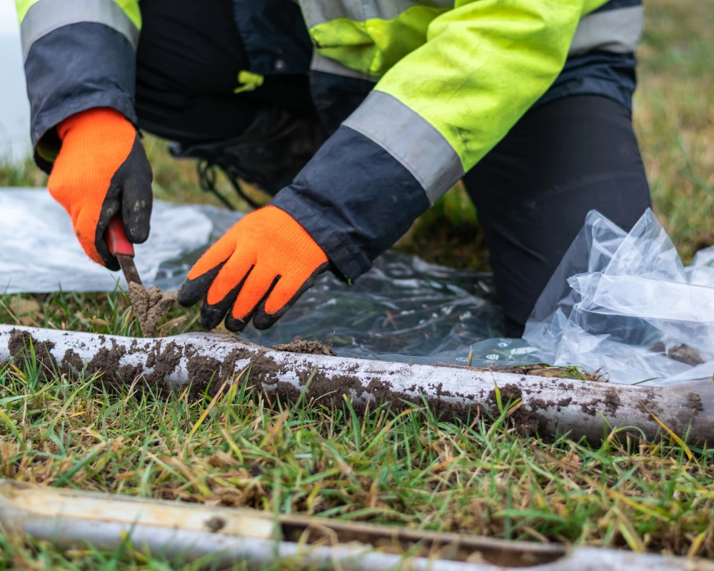
What Are Soil Borings?
Soil boring is a geotechnical investigation technique used to collect soil samples from below the ground surface. These samples are analyzed to determine the physical and mechanical properties of the soil, such as composition, density, moisture content, strength, and bearing capacity. The information gathered is crucial for designing safe and effective foundations for buildings, roads, bridges, and other infrastructure. Soil borings are also used in environmental assessments to detect contamination, monitor groundwater, and evaluate the suitability of land for agricultural or industrial use.
What is Groundwater Sampling?
Groundwater sampling is the process of collecting water from below the ground, usually through monitoring wells or direct push probes, to test for contaminants and assess the quality, chemistry, or environmental impact of groundwater at a site. It provides reliable, representative data about what’s happening beneath the surface, helping environmental professionals evaluate contamination, track pollutant movement, and make informed decisions about cleanup, redevelopment, or regulatory compliance.
How Can GPRS Support Soil and Groundwater Sampling?
Identifying safe boring locations is difficult when underground utilities are unknown or poorly mapped. Drilling without clearance can cause strikes, injuries, delays, and added costs. GPRS provides accurate maps of public and private utilities using utility locating and video pipe inspection. We clear drilling locations in advance to protect your team and infrastructure. Reliable utility data reduces risk, supports efficient sampling, and helps your team maintain safety while in the field. Contact GPRS today to support your soil and groundwater sampling efforts.
Quick Guide to Soil Vapor Assessment
Contaminants like petroleum and solvents can migrate as vapor and infiltrate buildings. A soil vapor assessment measures volatile organic compounds (VOCs) in the spaces between soil particles. It identifies if toxic vapors from contaminated soil or groundwater are moving into buildings, posing health risks to occupants. This assessment determines the need for mitigation, such as vapor barriers or venting systems.
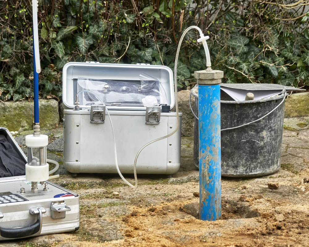
What are Volatile Organic Compounds (VOCs)?
Volatile organic compounds (VOCs) are carbon-based chemicals that evaporate easily. They can be found in common household products, such as paints, cleaners, adhesives, and industrial processes. These compounds can impact indoor air quality and health, especially in enclosed spaces.
What are Semi-Volatile Organic Compounds (VOCs)?
Semi-volatile organic compounds (SVOCs) are a group of human-made chemicals that easily transition between solid/liquid and gas phases at ordinary temperatures. Common in indoor environments, they include plasticizers, flame retardants, and pesticides found in furniture, electronics, and building materials, often contained in dust and on surfaces.
What is Vapor Intrusion?
Vapor intrusion (VI) occurs when volatile chemicals migrate from contaminated soil or groundwater into buildings. It can expose occupants to hazardous compounds and complicate transactions and redevelopment if not addressed.
How Can GPRS Support Soil Vapor Assessment?
Installing vapor pins requires drilling through slabs, risking conduit strikes and damaging reinforcements, especially in buildings with little to no documentation. GPRS SIM-certified Project Managers use concrete scanning and utility locating to identify shallow utilities and reinforcement before drilling. We support vapor intrusion investigations with subsurface data, mapping, and modeling. You get accurate data that reduces disruption, prevents strikes, and supports compliance with health and safety regulations. Contact GPRS today to support your soil vapor assessment efforts.
Quick Guide UST & LUST Investigations
What are Underground Storage Tanks (USTs)?
USTs are tanks and associated piping buried underground to store petroleum or other hazardous substances. They are commonly found at gas stations, airports, truck fleet refueling facilities, automotive service stations, dry cleaners, and industrial facilities. USTs must be designed, installed, and maintained to prevent leaks and ensure environmental safety.
What are Leaking Underground Storage Tanks (LUSTs)?
LUSTs occur when underground tanks develop cracks, rust, or fail due to mechanical or structural issues. These leaks can release hazardous substances into the surrounding soil and groundwater, leading to significant environmental contamination.
Read more about USTs and LUSTs.
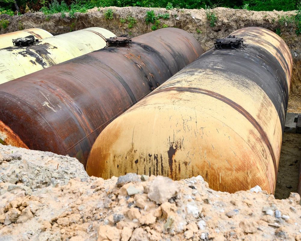
What is the Cause of Leaking Underground Storage Tanks (LUSTs)?
- Corrosion: Older steel tanks are prone to rust, leading to leaks.
- Structural Failure: Pressure changes and environmental stressors can cause tank deterioration.
- Improper Installation: Poor installation techniques may contribute to early failure.
- Accidental Damage: Construction and excavation activities can rupture tanks or piping.
- Neglected Maintenance: Lack of routine inspection and repair increases the risk of leaks.
How Can GPRS Support UST Investigations & LUST Locating and Mapping?
GPRS uses utility locating to safely locate orphaned, abandoned, or active UST systems. We provide CADD maps and conceptual site models (CSMs)to support remediation and compliance. Fast, accurate data helps you reduce risk, protect property value, and make informed decisions during due diligence. Contact GPRS today to support your UST & LUST investigations with locating and mapping.
What is a Conceptual Site Model (CSM)?
A conceptual site model or CSM is a 3D rendering of the subsurface data at the site that allows visualization of preferential pathways for delineation of liquids and may identify potential voids where soil vapor could create additional hazards.
Case Study: Gas Stations May Be Leaking Underground
Quick Guide to Delineation and Remediation
What is Delineation and Remediation?
Delineation defines the extent of soil or groundwater contamination, ensuring it is mapped accurately. It includes taking soil samples, installing groundwater monitoring wells, and using analytical chemistry to find where contamination exceeds legal thresholds.
Remediation is the cleanup, removal, or containment of those contaminants to protect human health and the environment. This can include treating the contamination on-site, such as injecting chemical agents into the ground or removing the contaminated material and treating it off-site.
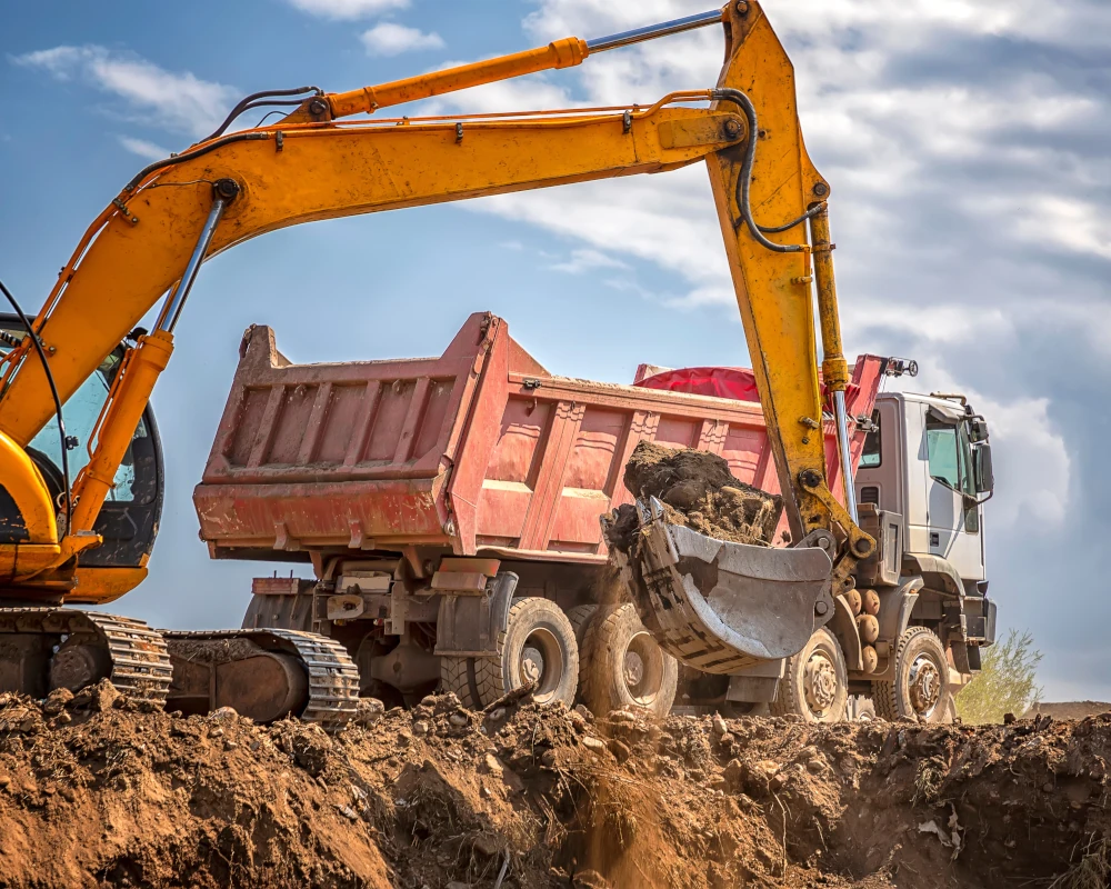
How Can GPRS Support Delineation and Remediation?
Tracking contamination across soil, groundwater, or soil vapor can be complex. GPRS provides scalable solutions from utility locating, concrete scanning, video pipe inspection as well as 3D laser scanning, CAD mapping, and BIM modeling to meet the needs of your project. Precise data and efficient workflows help you save time, reduce costs, and make confident decisions that support reaching No Further Action (NFA) or regulatory closure. Contact GPRS today to support your delineation and remediation efforts.
What is No Further Action (NFA) or Regulatory Closure?
A No Further Action (NFA) letter, or regulatory closure, is a formal document issued by an environmental agency (e.g., EPA, state DEQ) confirming that a contaminated site has been sufficiently investigated and remediated to meet safety standards. It signifies that no additional cleanup is required, allowing for property closure, financing, or redevelopment.
GPRS Utility Locating, Mapping, and Modeling Services
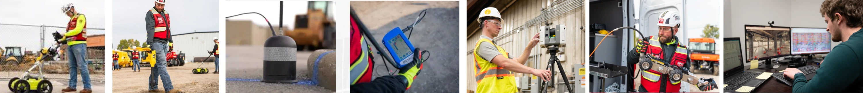
If you’re managing environmental concerns, or planning soil borings, vapor pin installations, or UST investigations, accurate subsurface data is essential for safety and cost control.
GPRS utility locating identifies underground utilities and UST components, helping you clear soil borings, install vapor pins, drill safely, and avoid damage.
We provide a full suite of services, including utility locating, concrete scanning, video pipe inspection, and 3D laser scanning, tailored to your project needs to support safe sampling, hazard identification, and remediation planning.
Our custom utility CADD maps protect infrastructure, while Conceptual Site Models (CSMs) reveal potential contaminant migration pathways and guide your next steps.
Deliverables are uploaded to GPRS’ SiteMap® GIS platform, giving you fast access to accurate data and insights to help you reduce risk, stay compliant, and make confident decisions.
As a trusted leader in damage prevention within the environmental sector, GPRS provides dependable results from the initial investigation through delineation, remediation, and project completion. With a nationwide network of Project Managers, we are prepared to mobilize quickly for projects across the United States.
How can we support your environmental due diligence and Phase II ESAs?