

.svg)
What are 2D Drawings or 2D CAD Drawings? – A 2D drawing or 2D CAD drawing is a 2D representation of a CAD model. A 2D CAD (computer-aided design) drawing is a technical drawing created using computer-aided design (CAD) software. 2D CAD drawings are flat representations of objects, show casing views from the top, front, side, or other angles and use geometric shapes, lines, arcs, and text to convey information about the size, shape, and layout of buildings and components. Some examples of 2D CAD drawings include floor plans, site plans, elevations, sections, details, isometric drawings, and reflected ceiling plans. Learn more about 2D CAD drawings.
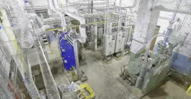
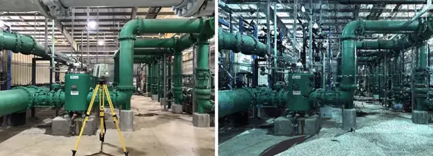
What is 3D Laser Scanning? – 3D laser scanning is a technology that employs lasers to measure an object's geometry to craft a digital 3D model. This technology is used throughout a number of industries and settings, such as architectural, construction, engineering, healthcare, historical, industrial, manufacturing, and more. 3D laser scanning captures three-dimensional data of objects, regardless of their surface features or size. Read more about 3D laser scanning.
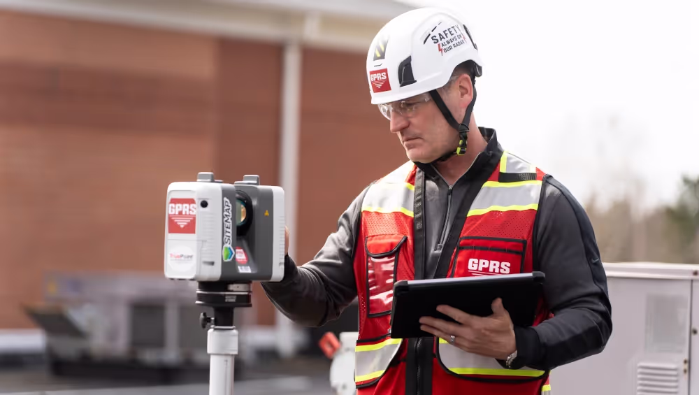
What is a 3D Laser Scanner? – A 3D laser scanner is an instrument which uses LiDAR (light detection and ranging) to measure and record precise locations and distances, ultimately producing a point cloud file. The technology enables users to produce highly accurate digital measurements and images quickly and easily.
What is 3D Scanning? – 3D scanning is the process of analyzing a real-world object or environment to collect existing conditions documentation data. The collected data can then be used to create 2D CAD drawings, 3D BIM models, 3D mesh models, virtual tours, digital twins, floor plans and more.
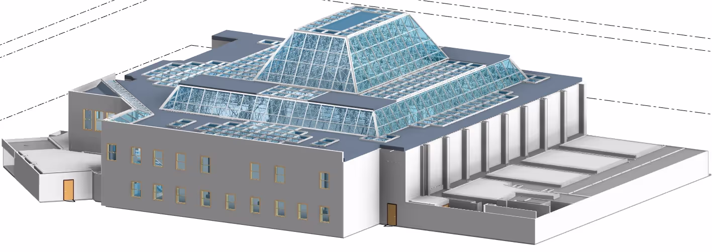
What are 3D Models or 3D BIM Models? – 3D models are accurate digital representations of a building or site to facilitate design, construction, and operational processes. 3D models provide users with the ability to break down architectural, structural and MEP building features and see how they fit into a single finalized structure. Users can isolate and alter walls, columns, windows, doors, etc. to support the planning and design needs of any project. Read more about 3D BIM models.
Accuracy – How close a measurement is to its true value.
What is Airborne Laser Scanning? – Airborne laser scanning is a measurement system in which pulses of light (most commonly produced by a laser) are emitted from an instrument mounted in an aircraft or drone and directed to the ground in a scanning pattern.
Alignment –The process of aligning two objects in a common coordinate system. Commonly refers to aligning scan data to known coordinates or to reference objects in construction and engineering applications.
What is an As-Built? – An as-built is an object’s real-world condition and appearance. As-builts are data, drawings, models, or plans that represent the existing conditions of a project site, building, or facility. Buildings can go through many modifications during the construction process. For example, the location of a wall, window, or system component can be moved or relocated. As-builts provide an accurate record of the current building information, including the layout, dimensions, and material specifications of architectural, structural, and MEP features, walls, windows, doors, stairs, roof, railings, exposed columns, beams, equipment, piping, and ducts, etc. Read more about as-builts using 3D laser scanning.
What is AutoCAD? – AutoCAD is Autodesk's CAD software that can be used to create precise 2D and 3D drawings and 3D BIM models, as well as electrical diagrams, construction drawings, and much more. AutoCAD has become a generic term and is considered the industry standard.
What is AutoCAD Civil 3D? – AutoCAD Civil 3D is a civil engineering design and documentation software that supports building information modeling (BIM) workflows inside AutoCAD.
What is BIM? – BIM stands for building information modeling and is an intelligent software modeling process that engineers, general contractors, facility managers, and architects can use to collaborate on a building’s design, construction, and operation. It’s more than just a model. It’s a process of collecting and managing data throughout a building’s entire life cycle.
What is Computer Aided Design or CAD? – Computer aided design, better known as CAD, is the use of computer-based software to aid in the design process. CAD software is frequently used by engineers and designers. CAD software can be used to create 2D drawings or 3D models.
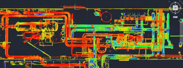
What is a Colorized Point Cloud? – A colorized point cloud contains the RGB value of the raster pixel that has the same location.
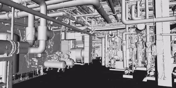
What is a Colorized Triangulated Mesh? – A colorized triangulated mesh is a visualization of point cloud data that basically connects the dots to form triangles. In a colorized triangulated mesh, RGB colors from photos are applied to the points to colorize the mesh.
What is a Datum? – A datum is any level surface, line, or point used as a reference. It is also a basis for horizontal control surveys, consisting of the longitude and latitude of a certain point.
What is Decimation? – A decimation refers to reducing the number of samples in a population. In 3D scanning, decimation usually refers to lowering the number of points reported from the scanner on a surface without distorting the detail or color. Decimation is used when there area large number of unnecessary overlapping points or surface mesh triangles.
What Are Degrees of Freedom? – Degrees of freedom describes the number of directions of movement and refers to how the position and orientation of an object is described relative to a coordinate system. In 3D laser scanning it usually consists of three linear translations (X, Y, and Z) and three rotations about the three axes (pitch, yaw, and roll).
What is Design-Intent? – Design-intent is the schematic representation of something, the structure as it was originally designed in a CAD environment. Design-intent deliverables are shown as a "best fit" to the point cloud working within customary standards, such as walls being modeled 90 degrees perpendicular to floor, pipes and conduit modeled straight, floors and ceilings modeled horizontal, and steel members modeled straight. This will produce cleaner 2D drawings and will allow for easier dimensioning of the scan area. The deliverables will not exactly follow the scan data to maintain design-intent standards. The majority of users will want this option for their deliverables.
What is Deviation in 3D Laser Scanning? – Deviation refers to the difference in the size and shape of an as-built environment versus its design specifications.
What is a Digital Twin? – A digital twin is a virtual model that accurately represents an existing physical space. It digitally represents a building’s architecture, structure, and systems. The most useful purpose of digital twin technology occurs during the construction design and planning process. A digital twin can be used to plan for building improvements, improve efficiencies, and optimize workflows, which can then be applied back to the actual physical asset. In a digital twin environment, ideas can be tested with few limitations. Read more about digital twins.
What is Digital Archiving? – Digital archiving is storing data digitally. Objects can be scanned and processed for digital archiving purposes.
File Format – Data published in a type of file compatible with end use. Such as .DWG, .DGN, .E57, .RCP, .RVT, .LGS, .STP, .IGES, .IFC, .OBJ, .STL, etc.
What is a Fillet? – A fillet in 3D laser scanning is a surface that connects two or more faces. This surface is usually an arc.
What is the Difference Between Intensity Level & Black and White Laser Scans? –The options for construction-grade 3D laser scanning are intensity, black and white, or greyscale. This refers to the coloring of the point cloud inside of software such as Revit, Recap, and TruViews. Data can be viewed in RGB, intensity, black and white or greyscale. The scanner does not need light to capture information in greyscale, black or white, or intensity, but color scans do require adequate lighting.
What are Laser Based 3D Scanners? – Laser based 3D scanners use a process called trigonometric triangulation to accurately capture a 3D shape as millions of points. 3D laser scanners work by projecting a laser line or multiple lines onto an object and then capturing its reflection with a single sensor or multiple sensors. The sensors are located at a known distance from the laser's source. Accurate point measurements can then be made by calculating the reflection angle of the laser light.
What are Laser Pulse-Based 3D Scanners? – Laser pulse-based scanners, also known as time-of-flight scanners, are based on a very simple concept: the speed of light is known very precisely. Thus, if the length of time a laser takes to reach an object and reflect back to a sensor is known, the distance from sensor to object is known. These systems use circuitry that is accurate to picoseconds to measure the time it takes for millions of pulses of the laser to return to the sensor and calculate a distance. By rotating the laser and sensor (usually via a mirror), the scanner can scan up to a full 360 degrees around itself.
What is a Laser Phase-Shift 3D Scanner? – A laser phase-shift system is another type of time-of-flight 3D scanner technology, which conceptually works similarly to pulse-based systems. In addition to pulsing the laser, these systems also modulate the power of the laser beam, and the scanner compares the phase of the laser sent out and returned to the sensor. Phase shift measurements are typically more accurate but are not as flexible for long range scanning as pulse-based 3D scanners. Laser pulse-based 3D scanners can scan objects up to1000m away while phase shift scanners are better suited for scanning objects up to 300m or less.
What is LiDAR? – Light Detection and Ranging or LiDAR – is a remote sensing method that uses light in the form of a pulsed laser to measure ranges(variable distances) to the earth. These light pulses—combined with other data recorded by the scanning system — generate precise, three-dimensional information about a site and its surface characteristics. Read more about LiDAR.
What Does it Mean to Merge Data? – Merging data sets in 3D laser scanning means combining two or more scan data sets into one larger data set.
What is a 3D Mesh Model? – A 3D mesh model is a visualization of point cloud data that basically connects the dots to form triangles. A 3D mesh can be created from a point cloud in .fbx, .stl, .obj, and .ply file formats. Meshes are volumetrically accurate, high density and high resolution. Meshes allow users to view the object’s geometry inside a CAD environment without having to navigate a point cloud. Meshes can be used for representing scanned elements with fine, organic details such as monuments and statues that are otherwise difficult to reproduce in CAD. Read more about 3D mesh models.
What is Mobile Mapping or Mobile Laser Scanning? – Mobile mapping or mobile laser scanning is a technology on a mobile system for generating highly accurate 3D point clouds and has many potential applications.
What is Noise in Relation to Point Clouds? – The “fuzziness” of the point cloud. Noisy points show up in every raw data set, regardless of the scanner, because the physical behavior of the laser sensor creates random imperfections in the data.
What is 3D Photogrammetry? – 3D Photogrammetry is a three-dimensional coordinate measuring technique that uses photographs as the fundamental medium for metrology or measurement.
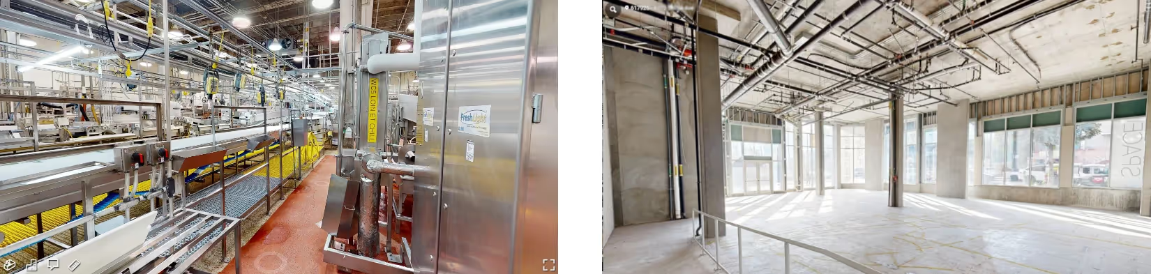
Photogrammetry uses a 3D Matterport camera, which can also be equipped with LiDAR, to digitally document buildings, facilities, and sites with high-resolution photographs. Cameras or LiDAR sensors can be fixed on a tripod, attached as a wearable device, flown via aerial drone, or even affixed to a crane for an aerial view of the site. 4K HDR photographs are taken from different positions and angles to capture a 360° view of the site. LiDAR technology captures three-dimensional site coordinates (x,y,z) in the form of a point cloud.
The photographs and point clouds captured with photogrammetry can be used to create digital twins, virtual tours, floorplans, 2D CAD plan views, 3D models, and more. The data captured provides clients enough spatial detail to accurately measure depths and distances from one point to another. The point cloud from photogrammetry can be used to create a building information model (BIM) or for geographic information system (GIS) data generation and visualization. How is 3D photogrammetry used in construction?
What is Precision? – Precision is the repeatability of performing a measurement in 3D laser scanning.
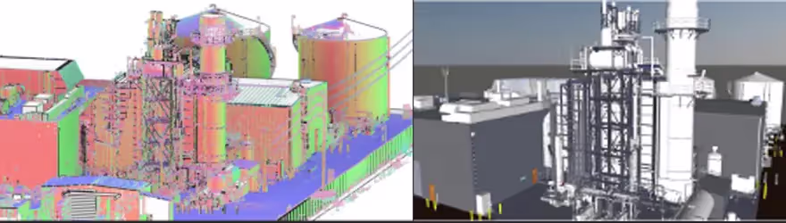
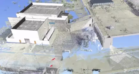
What is a Point Cloud? – A point cloud is a collection of individual data points in a three-dimensional plane with each point having a set coordinate on the X, Y, and Z axis. The point cloud is the output of the 3D laser scanning process. Point clouds are typically represented by .ptg or .e57 point cloud files and Autodesk Recap files in .rcs and .rcp format. This is also referred to as the raw scan data from the laser scanner.
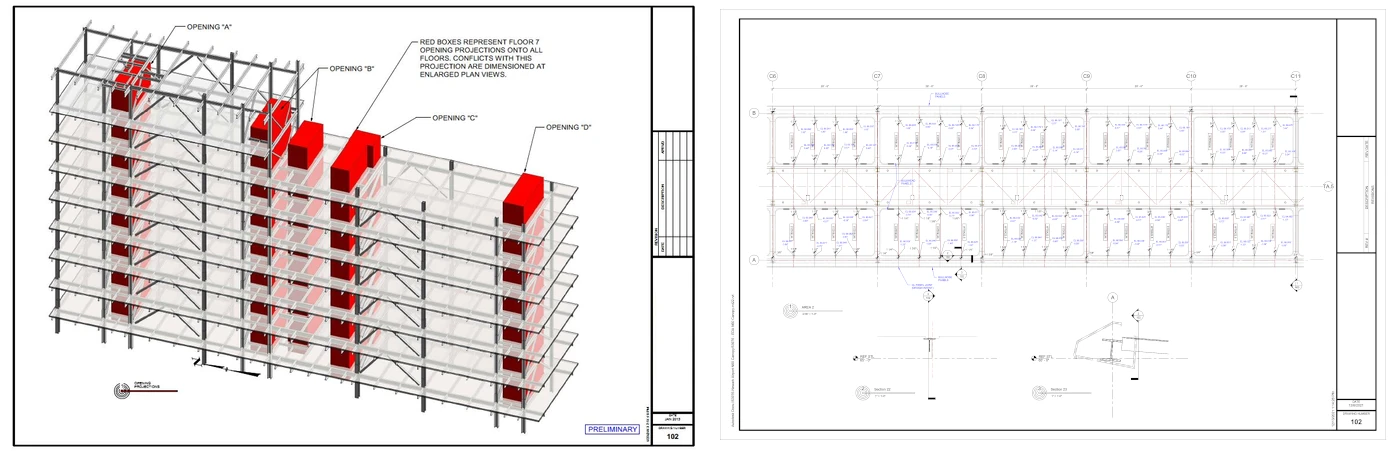
What is a Quality Inspection in Construction? – A quality inspection is the process of evaluating a building or site and comparing it to the design specifications that are described in the project’s CAD file. Inspection is an “as-built” vs “as-designed” comparison.
What is Registration for 3D Laser Scanning? – Registration is the process of compiling or “tying together” individual laser scans into a cohesive point cloud.
What is a Rendering in 3D Laser Scanning?– A rendering is a graphical representation of a computer model. It is often used to describe the visual output of CAD and modeling software. By rendering a computer model, users can often add characteristics and effects to its surfaces and features.
What is the Resolution of a Point Cloud? – Resolution stands for the spacing of points in a grid. The higher the resolution, the more data that will be captured. Likewise, the lower the resolution, the less the detail.
What is Revit? – Revit is a building information modeling (BIM) software by the company Autodesk. It’s generally used by architects, structural engineers, mechanical, electrical, and plumbing (MEP) engineers, designers, and contractors to view point clouds and foster collaboration. Autodesk Revit allows users to create, edit, and review 3D models in exceptional detail, including the point cloud. Part of the Autodesk Suite, it is easily interchanged with AutoCAD, Navisworks, and other Autodesk Suite software. It can also export IFC file formats for use in other programs.
What is ReCap? – Recap is an easy-to-use program that works with native point cloud files created with laser scans. The “ReCap” part of the name is short for “reality capture”, and the system is included in the Autodesk Design Suite. ReCap is the gateway from point clouds to all of Autodesk’s software.
What Does Scan Mean? – Scan stands for measuring the site, capturing data, and transferring the measured points to the computer. It also refers to the computer file that is based on the physical object, i.e., the x, y, z coordinates that represent physical measurements taken by the laser scanner.
What is Scan to BIM? – Scan to BIM is a process that uses 3D laser scanning to create a digital model of a site or building, which is then used to create a building information modeling (BIM) model. BIM is a software process that allows architects, contractors, and engineers to collaborate on a building's design, construction, and operation. Everything you need to know about Scan-to-BIM.
What are Short Range 3D Scanners? – Short range 3D scanners typically utilize a laser triangulation or structured light technology.
What is SLAM? – SLAM stands for simultaneous localization and mapping. SLAM's purpose is to move through a given space to create a digital map of that space that users can refer to. In 3D scanning, a SLAM algorithm uses the LiDAR sensor to track a precise estimate of the point cloud scanner’s position as it moves through a space. The mapping software, in turn, uses this data to align your point cloud properly in space.
What are Solids in BIM Modeling? – Solids can be used to graphically represent the mass of a subassembly shape and can be used to extract mass properties, such as volume.
What are Targets in Laser Scanning? – Targets are physical objects that 3D laser scan Project Managers set up on site that scanning software uses to tie together multiple scans. Also known as reference markers.
What is Tessellation? – Tessellation generally refers to filling a surface plane or surface with shapes that create no gaps or holes. In 3D laser scanning, this concept applies to wrapping a mesh around a CAD body. A jigsaw puzzle is a great real-world example of a collection of tessellated shapes.
What is Terrestrial Laser Scanning? – Terrestrial laser scanning, also referred to as terrestrial LiDAR (light detection and ranging) or topographic LiDAR, acquires XYZ coordinates of numerous points by emitting laser pulses toward these points and measuring the distance from the device to the target.
What is Time of Flight? – Time of flight refers to 3D laser scanners that calculate measurements based on the time it takes for the laser beam to detect a surface and report back.
What is Triangulation is 3D Laser Scanning? – Triangulation is using trigonometric functions to calculate measurements, used in certain types of 3D laser scanners to determine point locations based on transmission and reflection positions of the laser beam. In 3D modeling, triangulation also refers to the generation of triangles out of point cloud data in creating 3D surfaces.
Uncertainty –Uncertainty stands for what is the highest probable absolute difference between the measured value and the true value.
What is a 3D View? – There are options to select predefined standard orthographic and isometric 3D views in AutoCAD by name or description.
What is a Base View?– A base view is the first view created in a drawing. The base view is the source for subsequent views and controls scale and alignment.
What is a Detail View? – A detail view is an enlarged view of a specified portion of another drawing view. By default, the scale of the detail view is double the scale of the parent view, but users can specify any scale. A detail view is created without alignment to its parent view.
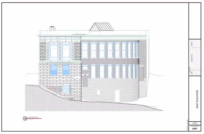
What is an Elevation View? – The definition of an elevation view drawing is the view that users would see in real life if they stood on the floor or ground and looked at the wall. This view can be either an exterior or interior view.
What is a Floor Plan? –A floor plan is a base view attributed to a level of a floor of a building or site. A floor plan is a view of a building drawn as if users were looking at it from the ceiling. Architects, engineers, and builders use floor plans for design and retrofit projects.
What is an Orthographic View? – An orthographic view is when orthographic drawings display two-dimensional views of structure, piping, valves, equipment, etc., in 3D models.
What is a Perspective View? – A perspective view is a two-dimensional representation of a three-dimensional space, where the apparent size of an object decreases as its distance from the viewer increases.
What is a Projected View? – A projected view is an orthographic or isometric view that is generated from a base view or other existing view. Users can create multiple projected views in a single operation.
What is a Section View? – A section view is a view created by sketching a line that defines a plane used to cut through part of abuilding. Users draw the cutting line when users create the view or select it from a sketch associated to the parent view. The cutting line can be a single straight segment or multiple segments. The cutting line arrowheads on the base view automatically orient to reflect the position of the section view relative to the base view.
What is a Site Plan? – A site plan, sometimes referred to as a plot plan or a site map, is a drawing that depicts the existing conditions of a given area. The site plan shows the layout of a property or site, including the location of buildings, structures, and site details.
What is Watertight for a 3D Mesh Model? – In a watertight mesh, every hole is filled automatically. The software does a polygonization, i.e. adds triangles, based on the scanned data. The holes are filled up based on the surrounding data. This kind of mesh is suitable for 3D printing or virtual reality. In an unwatertight mesh, the model remains open.
Read more about GPRS 3D Laser Scanning Services.