industry insights
Featured Articles
Why Do You Need Updated As-Builts on Your Next Project?
Is Utility Mapping Worth the Cost?
industry insights
Is There a Cost-Effective Construction Documentation Method?
3D Photogrammetry is a Low-Cost Investment with Many Benefits
Imagine having instant access to your site’s spatial data at any point during the construction process, including measurements, floor plans, and virtual tours for a fraction of the cost of 3D laser scanning. How would that change your team’s workflow and productivity?
Many clients would benefit from a walkthrough of their site during different stages of construction. 3D photogrammetry can deliver a 3D virtual record of the project before, during, and after construction. Now imagine having this as-built documentation quickly at a low-cost.
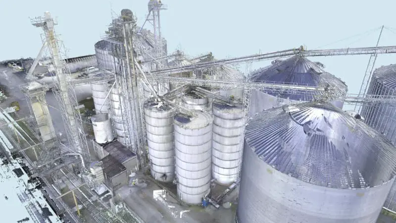
GPRS 3D photogrammetry services use a professional-grade 3D camera to capture high-resolution 360° images and LiDAR point clouds. GPRS 3D photogrammetry offers 20mm accuracy within a 10m range and has a maximum of 100m scanning range. It takes less than 20 seconds per scan location to collect more than 100,000 data points. Clients receive an immersive and interactive walkthrough of their building’s architecture, structure, utilities, and MEP systems in real-time.
Photogrammetry is a low-cost existing conditions construction documentation investment that can quickly transform sites into digital twins. The technology captures layout and dimensional data in color, and clients can import e57 point clouds and .OBJ files directly into CAD or BIM modeling software.
Existing condition documentation by way of 3D photogrammetry can be used to design modifications and upgrades before beginning construction. It can record the location of utilities, concrete reinforcements, and MEP installations. It can also provide progressive capture on a jobsite so everyone can see what’s been done and what milestones are still to be completed. Plus, it can provide a virtual tour of a site upon project completion.
Recent GPRS 3D Photogrammetry Services
A power company that delivers electricity and gas to Massachusetts customers and communities requested a GPRS WalkThru 3D of the utility locate for their site.

A water company that manufactures and supplies water dispensers and multi-gallon bottled water to retail locations requested GPRS 3D photogrammetry of their facility.

An architect requested GPRS as-builts prior to remodeling existing warehouse space and the installation of new machining and manufacturing equipment. They needed to understand all underground electrical, plumbing, sewage, and compressed air lines before construction to make sure they did not damage the existing systems.

To efficiently plan and manage your project and keep it on time and on budget, reach out to one of GPRS’ 500 Project Managers located across the United States. Our Project Managers will quickly mobilize to document your site in photo-realistic 3D. Our in-house Mapping & Modeling Team rectifies the 3D photogrammetry to digitize your site into WalkThru 3Ds, floor plans (FLRPLN), progressive capture (PRO CAP), and TRUBUILTs.
With 3D photogrammetry, clients can digitize and view their space, get accurate measurements, design modifications, and more. GPRS offers project executives, general contractors, and field teams a comprehensive set of add-on tools to receive as-built data, make informed decisions, and optimize construction design and workflows.
WALKTHRU 3D VIRTUAL TOURS
Receive accurate existing condition documentation, as-builts, and dimensional information in real time with WalkThru 3D Virtual Tours. GPRS uses 3D photogrammetry to provide immersive site walkthroughs and 3D virtual tours that allow project teams, designers, and stakeholders to remotely walk through a site or facility. WalkThru 3D eliminates travel and improves communication and collaboration. It also allows clients to intelligently visualize their site, identify potential issues, and make informed decisions without the need for physical presence.
WalkThru 3D can be delivered digitally and accessed via SiteMap® so that your virtual tour can be downloaded, saved, and shared to any laptop, tablet, or smartphone, and is accessible 24/7.

FLRPLN
The GPRS Mapping & Modeling Team can take the rectified, real-time 3D photogrammetry from WalkThru 3D and create an accurate existing condition as-built floor plan of a project site for design planning, risk mitigation, and emergency planning purposes. FLRPLN is a precise 2D CAD construction drawing that provides project teams accurate layout, dimensions, and details of a building or structure. It helps everyone visualize the project site, communicate with clients and contractors, and comply with codes and regulations. FLRPLN can be used to identify potential hazards, develop emergency action procedures, safety protocols, and train personnel on site-specific procedures.
GPRS FLRPLN can be delivered digitally and accessed via SiteMap® so that it can be downloaded, saved, and shared to any laptop, tablet, or smartphone and is accessible 24/7.

PROCAP
PRO CAP Progressive Capture can document construction progress from start through completion with 3D photogrammetry. GPRS’ Project Managers can accurately record the precise details of a project site from the location of utilities and concrete reinforcements to MEP installation locations, and more with 3D rectified imagery. We can provide PRO CAP on a regular schedule for the life of a project, whether it be bi-weekly, monthly, or customized to a client’s needs.
By capturing scans regularly, clients can track the evolution of the site, monitor construction milestones, manage project timelines, and ensure that work is proceeding according to schedule. Accurate record images can help to avoid clashes, change orders, and streamline communications.
PRO CAP Progressive Capture is valuable when managing projects from a remote location or managing multiple project sites.
PRO CAP scans can be delivered digitally and accessed via SiteMap® so that they can be downloaded, saved, and shared to any laptop, tablet, or smartphone and are accessible 24/7.

TRUBUILT
Eliminate outdated and inaccurate as-builts with TRUBUILT, real-time reality capture 2D CAD plan views of infrastructure – above and below ground. TRUBUILTs are accurate existing condition as-builts of a site or facility. They break down information silos and allow team members to collaborate with comprehensive, layered, data. TRUBUILT as-builts can serve as comprehensive documentation for reference, maintenance, and renovation projects.
Clients can access, copy, download, and share TRUBUILT as-builts via SiteMap® to keep their projects on time, on budget, and safe.

What is SiteMap®?
GPRS recently developed SiteMap®, a cloud-based user-friendly software that quickly and securely delivers 3D photogrammetry data, maps, and models for construction and infrastructure projects. SiteMap® provides customers with GPRS accurate as-built information – from our 99.8%+ accurate utility maps & concrete imaging results to CAD drawings and fully integrated 3D BIM models that meld 2-4mm accurate aboveground as-builts & below ground infrastructure to create a digital twin of any site.
3D photogrammetry can be accessed via SiteMap® to view site documentation, make informed decisions, coordinate work, and minimize errors. Clients can share data easily with team members, digitally measure inside 3D photogrammetry files, and use features like annotation, markup, and feedback to communicate with team members, clients, and contractors.

Why GPRS? The GPRS Difference.
GPRS reality capture services Intelligently Visualize The Built World® to create a digital representation of the real-world conditions of a construction site or an existing building.
GPRS utilizes 3D photogrammetry for reality capture to deliver accurate as-built data to construction professionals to make informed decisions and manage and execute projects. 3D photogrammetry enhances accuracy, efficiency, safety, and communication throughout the entire construction process, from initial design to project completion.
If your project requires a higher level of accuracy, GPRS also offers 3D laser scanning that provides 2-4 millimeter accurate records of existing as-built conditions. 3D laser scan data can be processed by our in-house Mapping & Modeling Team to deliver point cloud files, 2D CAD drawings and 3D BIM models to help you plan, design, manage, and build better.
With over 500 Project Managers in every major city across the United States, GPRS has an unmatched nationwide service network that makes it quick and easy to find local experts. GPRS specializes in 3D laser scanning, 3D photogrammetry, asset digitization, 3D virtual tours, digital twins, scan to CAD, and scan to BIM for the in the AEC industry.
What can we help you visualize?
Frequently Asked Questions
What is the Meaning of Photogrammetry?
When you break down the word photogrammetry – “photo” refers to light, “gram” means drawing and “metry” refers to measurements. Photogrammetry uses photos to gather measurements from which drawings, maps, models, and virtual tours can be created.
What are the Benefits of Photogrammetry?
- Permanent record of existing conditions
- Fast 2D and 3D data collection
- Accurate virtual models of physical assets, structures, and systems
- Digital twins and virtual site tours
- Eliminates the need for site revisits
- Minimal disruption to environment
- Saves time compared to conventional ground surveys
- Non-intrusive and cost effective
- Expedites decision making, increasing project efficiency
What Industries Use Photogrammetry?
Photogrammetry can be used in many industries: construction, civil engineering, structural engineering, telecommunications, military intelligence, agricultural, cultural heritage & preservation, real estate, film & entertainment, public safety, forensics & accident investigation, archaeology, and more.
How GPRS Manages Large Point Cloud Datasets
Engineers and contractors have more project data than ever before thanks to 3D laser scanning technologies such as LiDAR (light detection and ranging) and photogrammetry. These methods of reality capture collect millions of data points and store them in the form of a point cloud. The point cloud generated from laser scanning and photogrammetry is important for construction planning because it provides a highly accurate and detailed representation of a building or site.
What is a Point Cloud?
According to US CAD, “laser scanners digitally capture objects using laser light. The result is a point cloud consisting of millions of points that produce a highly accurate 3D representation of the as-built conditions. A point cloud can be easily imported into leading CAD and BIM software solutions to further use in the design and construction process.”
GPRS defines a point cloud as a collection of data points in a 3D coordinate system. Each point in the point cloud is defined by its XYZ coordinate, and may also include additional attributes such as color, intensity, and reflectance. The reflectance characteristics of each LiDAR point cloud document the reflectance properties of points to known values (high, medium, low) which are characteristic of commonly classified features, such as vegetation, asphalt roads, buildings, and water bodies.
To 3D laser scan a site, a GPRS Project Manager positions a laser scanner at various locations, taking individual scans from varying viewpoints to capture comprehensive site data. A single scan from a 3D laser scanner can generate millions of individual points or XYZ coordinates, each representing a specific location in the 3D space. The captured points record every surface color, detail, and texture, creating a direct representation of the scanned project site with 2-4 millimeter accuracy.
The size of a point cloud can vary significantly depending on several factors, including the resolution of the scan, the area covered, and the level of detail captured. For example, a laser scan of a large building could produce a point cloud with billions of points. Higher density scans capture more points per area and provide a more detailed and accurate representation of a space, resulting in an even larger point cloud file size.
Projects can include hundreds of laser scans, stored in large files that can create datasets in excess of a terabyte. Registering, storing, and manipulating these large datasets can be challenging.
Why is Point Cloud Registration Important?
Registering a 3D laser scan point cloud involves aligning multiple scans of the same area taken from different positions into a single, coherent point cloud. The registration process can be complex and time-consuming, especially for large and detailed point clouds. Getting the registration right ensures the most accurate measurements, drawings, and models.
GPRS Project Managers are trained to acquire data in ways that allow for good, tight registration. They capture multiple scans of the site from different positions, ensuring that there is sufficient overlap between scans.
The Mapping & Modeling Team combines the aligned scans into a single, merged point cloud. The team converts raw scan data to Autodesk ReCap scan files (RCS files) and project files (RCP files). They perform quality checks on every point cloud, removing noise, setting the coordinate system, checking for any misalignments or inconsistencies, and validating the precision of the registration. The team makes sure all the scans fit together exactly as they should, so that a client’s point cloud and models will have tight lines and accurate measurements.
GPRS has a team of experts who can register datasets of any size. We have completed projects with thousands of individual scans, on sites that are hundreds of acres large, and with miles of piping. No matter how big or small a project, GPRS provides client’s with the most precise point clouds to create accurate 2D drawings and 3D models.
How Does GPRS Manage Large Point Cloud Data Sets?
Once the point cloud is registered, it can be exported to a client for analysis, visualization, or processing. By consulting with the GPRS Mapping & Modeling Team, we can implement different strategies to effectively manage large point cloud datasets for our client’s architecture, engineering, and construction projects.
- Data Storage: We recommend that our clients use a storage solution that can handle large datasets efficiently. This might include cloud storage services, network-attached storage (NAS), or dedicated storage servers.
- Data Compression: We can use data compression techniques to reduce the size of the point cloud files without significantly affecting their quality. GPRS is also able to reduce the file size of the point cloud by creating unified RCS files or dividing a project into multiple RCS files to use individually.
- Data Streaming: Instead of loading the entire point cloud into memory at once, we recommend streaming techniques to load and process the data in chunks. This can help reduce memory usage and improve performance.
- Level of Detail (LOD): Our Mapping & Modeling Team can generate multiple levels of detail for the point cloud data, with higher levels of detail for areas of interest and lower levels of detail for less important areas. This can help reduce the overall size of the dataset while still maintaining important details.
- Data Filtering: We can use filtering techniques to remove unnecessary or redundant points from the dataset. In ReCap, we can drastically reduce the point cloud file size by changing the spacing between the unified points. We can use point decimation techniques to reduce the point cloud resolution by omitting a certain number of pixels in rows, columns, or both columns and rows. We can also remove points that are outside the area of interest or that represent noise in the data. For example, we can crop the data down to not show superfluous data, like removing data from across the street.

What Are the Applications of Point Cloud Data?
Point cloud data has become the new standard in pre-design planning for the architecture, engineering, and construction industries. Having a virtual dataset of the project site gives our clients’ the ability to utilize real-time data for decision making.
Point clouds are used to create 2D CAD drawings and 3D BIM models to expedite the planning, design, construction, and management of construction and infrastructure projects.
GPRS is a leading provider of 3D laser scanning and 3D photogrammetry services, helping clients to successfully complete their most complex projects with accurate as-built documentation, point clouds, 2D CAD drawings, and 3D BIM models.
What can we help you visualize?
Frequently Asked Questions
What is photogrammetry?
Photogrammetry is the process of capturing images and stitching them together to create a digital model of a structure or site for visualization and analysis. It is a fast way for architecture, engineering, and construction teams to document accurate as-built site conditions.
What is 3D laser scanning?
3D laser scanning uses LiDAR technology to capture as-built documentation of existing buildings or sites. Once data is acquired, a point cloud is generated and used to develop 2D CAD drawings or 3D BIM models, expediting the design, planning, and development of projects.
What scanners are used for data collection?
GPRS utilizes a terrestrial 3D laser scanner for data collection, as they are able to document vertical structures, such as buildings and facilities. These scanners sit on a tripod and can take 1-3 minutes to complete each scan, depending on the project requirements. Terrestrial laser scanners are known to produce the most accurate point clouds due to the fact that they are stationary. A laser scanner can only capture what is in its line of sight. Scanners are positioned around a site and take individual scans from varying viewpoints to capture complete site data. The captured points record everything from surface detail and texture, to color, creating a direct representation of the scanned project site.
Navigating the Currents: Addressing the Critical Threats to Water Infrastructure
Water infrastructure is the backbone of modern society, ensuring the safe delivery of drinking water to our homes and businesses.
This vital system, however, is under siege from various threats that jeopardize its integrity and functionality.

Aging Infrastructure: A Ticking Time Bomb
One of the most pressing threats to water infrastructure is its age. In many parts of the world, water systems nearing the end of their designed lifespans. This aging infrastructure is more susceptible to leaks, breaks, and system failures.
The American Society of Civil Engineers (ASCE) has consistently given poor grades to the nation's water infrastructure, highlighting the urgent need for upgrades and repairs. In its most recent Infrastructure Report Card, the ASCE gave our drinking water infrastructure a C-.
“Our nation’s drinking water infrastructure system is made up of 2.2 million miles of underground pipes that deliver safe, reliable water to millions of people,” the ASCE wrote.
“Unfortunately, the system is aging and underfunded. There is a water main break every two minutes and an estimated 6 billion gallons of treated water lost each day in the U.S… Enough to fill over 9,000 swimming pools…”
The Silent Culprit
Leaks are a pervasive problem in water distribution systems. They not only waste valuable water resources, they also lead to significant financial losses for utilities. Advanced leak detection technologies, like acoustic sensors and smart water meters, are becoming increasingly important in identifying and locating leaks early, before they escalate into major breaks. By investing in these technologies, utilities can reduce non-revenue water (NRW) loss and extend the life of their infrastructure.
Non-Revenue Water Loss: An Economic Drain
Non-revenue water (NRW) loss, which includes water lost to leaks, theft, and metering inaccuracies, is a financial drain on water utilities. It represents water that is produced and treated but not billed to customers, leading to lost revenue. Reducing NRW is essential for the financial sustainability of water utilities and for ensuring the efficient use of water resources. Implementing comprehensive water audit programs and adopting smart water management solutions can help utilities minimize NRW and improve their bottom line.
Inflow and Infiltration: The Hidden Flood
Inflow and infiltration (I/I) are processes that allow extraneous water to enter sewer systems, often overwhelming wastewater treatment plants and leading to untreated sewage discharges into the environment. Inflow occurs when stormwater directly enters the sewer system through improper connections, while infiltration happens when groundwater seeps into the sewer pipes through cracks and leaks. `a multi-faceted approach, including repairing and replacing damaged pipes, disconnecting improper connections, and implementing green infrastructure to manage stormwater at its source.
Climate Change: A Rising Tide of Challenges
Climate change poses an increasingly significant threat to water infrastructure. Rising sea levels, more intense storms, and changing precipitation patterns can lead to coastal flooding, increased stormwater runoff, and more frequent and severe droughts. These challenges require water systems to be more resilient and adaptable. Investing in climate-resilient infrastructure, such as flood-resistant pump stations and drought-tolerant water sources, is crucial for ensuring the long-term sustainability of water systems.
Urbanization: The Pressure of Growth
Rapid urbanization is putting additional pressure on water infrastructure. As cities grow, so does the demand for water services, which can strain existing systems. Moreover, urban sprawl can lead to more impervious surfaces, exacerbating stormwater management challenges. Sustainable urban planning, including the integration of green infrastructure and smart water technologies, is essential for managing the impacts of urbanization on water systems.

GPRS Leak Detection Keeps Your Water Where it Belongs
The threats to water infrastructure are diverse and complex, but they are not insurmountable.
By prioritizing investments in modernization, embracing innovative technologies, and adopting sustainable practices, we can safeguard our water systems for future generations.
It starts by ensuring your water stays where it belongs.
Even a small leak in a water system can have big consequences. That’s why GPRS offers underground water leak detection services designed to mitigate the risk of NRW loss and other threats to your water infrastructure. We can quickly pinpoint a known leak when a problem has been identified, or proactively search for leaks along a domestic pressurized water or fire system for a municipality or facility.
GPRS uses two primary technologies for our leak detection services:
1. Acoustic Leak Detection
Acoustic leak detection involves using sophisticated ground microphones to listen for leaks coming from pressurized subsurface pipes. Our Project Managers (PMs) are acoustic leak detection specialists who are thoroughly trained to pinpoint leaking pipes’ specific sounds and frequencies.
Pipes made of metal, such as cast iron/ductile mains, smaller copper service lines, and steel pipes transmit water leak sounds over longer distances than pipes made of PVC or asbestos-cement. Accordingly, our PMs consider the pipe material and its size when determining how best to evaluate your water system. Small diameter pipes are more likely to transmit more sound than large diameter pipes, regardless of their material. Large diameter pipes transmit lower frequency sounds than small diameter pipes.
2. Leak Noise Correlators
Leak detection, or leak noise correlators are specialized electronic devices that professional leak detection service companies like GPRS use to quickly and accurately locate leaks in water lines. Sensors are placed on both sides of the pipe, and these sensors send information back and forth between each other via radio. An automated process identifies each suspected underground water leak location and displays it on the main control unit. The processing unit then compares this data with mathematical algorithms designed for the specific noise profiles of the pipe material being tested, determining where the leak is coming from between each sensor’s location.
Our Project Managers map out leaks using the data collected with leak detection correlators, then pinpoint the leaks using acoustic leak detection equipment.
From skyscrapers to sewer lines, GPRS Intelligently Visualizes The Built World® to keep your projects on time, on budget, and safe.
What can we help you visualize? Click below to schedule a service or request a quote today!
Frequently Asked Questions
How many miles of pipe can GPRS test for leaks in one day?
The amount of pipe we can test often depends on the experience of the leak detection specialist. Team members with many years of experience can test up to 10 miles of pipe a day on a metallic system (cast iron/ductile). Experienced leak detectors can test a contact point (hydrant/valve) within a minute before moving on to the next one. Leak detectors can work efficiently because they are trained to hear the specific tone that a leak produces compared to any other number of noises a general environment makes.
Why do you have to work in the early hours of the morning?
Our acoustic listening equipment is highly sensitive and amplifies leaks and other noises which mask leak signals during the day. If we work in city environments, there is often a significant amount of ambient noise. This noise includes airplanes, traffic, mowers, machinery, and most importantly, people using water. It is up to the leak detection specialist to determine if night work should be utilized to minimize all other noise to focus on the leak signal.
Why don’t I see any water at the location where you’ve pinpointed a leak?
Water finds the path of least resistance. Water can run through cracks in subsurface rock or make its way into storm, sanitary, and conduit piping. If the subsurface contains a high volume of sand, it will naturally flow farther down. There is no water visible on the surface in over 99% of the leaks we locate.
What is a Cross Bore – and How Does GPRS Help Prevent Them?
The underground infrastructure of our cities is a complex network of pipelines and cables, essential for providing utilities like gas, water, and telecommunications.
As urban areas expand and the demand for these services increases, the challenge of installing and maintaining this subsurface infrastructure grows. One significant concern that has emerged and grown with the advent of trenchless technology is the issue of cross bores.

What are Cross Bores?
A cross bore is a situation where a new utility line, typically installed using trenchless methods such as directional boring, inadvertently intersects and potentially breaches an existing underground utility, most commonly a sewer line. This unintended intersection can create a pathway for gas or other hazardous materials to leak into the sewer system, posing significant risks to public safety and the environment.

How are Cross Bores Created?
Cross bores are primarily a byproduct of trenchless technology, a method of installing underground utilities without open trench excavation. Techniques like directional boring allow for the installation of new pipelines with minimal surface disruption, making it an attractive option in urban settings. However, if the existing underground infrastructure is not accurately mapped or detected, there is a risk that the new line will intersect with existing utilities, resulting in a cross bore.
Mitigating Cross Bores
The mitigation of cross bores involves a combination of preventive measures and corrective actions:
Pre-Construction Utility Locating and Mapping
Before any trenchless construction begins, it is crucial to conduct thorough locating and mapping of the existing underground utilities. This can involve the use of ground-penetrating radar (GPR), electromagnetic (EM) locators, and other technologies to detect and document the location of existing lines.
Cross Bore Safety Programs
Utility companies and contractors should implement comprehensive cross bore safety programs that include best practices for planning, construction, and post-installation inspections. These programs are designed to prevent cross bores and ensure that any that do occur are quickly identified and addressed.
Coordination and Communication
Effective coordination and communication among utility providers, contractors, and regulatory agencies are essential to ensure that all parties are aware of the potential risks and are working together to mitigate them.
The Role of Sewer Line Inspections
Sewer line inspections, particularly through the use of CCTV-camera-equipped remote controlled sewer scope rovers, play a crucial role in the detection and mitigation of cross bores:
Detection of Cross Bores
Sewer scopes, which involve sending a camera down the sewer line, can provide a visual inspection of the interior of the pipe. This can help identify any signs of a cross bore, such as unusual obstructions or damage to the pipe that might indicate the presence of an intersecting utility line.
Post-Installation Inspections
After the installation of new utility lines using trenchless technology, it is important to conduct sewer line inspections to ensure that no cross bores have occurred. This is a critical step in the prevention of accidents and should be a standard practice in any trenchless construction project.
Maintenance and Monitoring
Regular sewer line inspections can also help in the ongoing monitoring and maintenance of underground infrastructure. By identifying potential issues early, such as small leaks or damage that could lead to a cross bore, proactive measures can be taken to prevent more significant problems.

GPRS VPI Services Help Mitigate Cross Bore Risk
Cross bores represent a significant challenge in the management of underground utilities, particularly with the increasing use of trenchless technology.
GPRS’ utility locating, utility mapping, and video pipe inspection services provide you and your team members with a comprehensive understanding of the subsurface infrastructure in your project area, so you know where it’s safe to trench or bore, and where breaking ground could have catastrophic consequences.
Our team of over 500 SIM and NASSCO-certified Project Managers (PMs) are strategically stationed across every major market in the U.S., so you always have professional utility locating and mapping, and sewer line inspection services near you.
From skyscrapers to sewer lines, GPRS Intelligently Visualizes The Built World® to keep you on time, on budget, and safe.
What can we help you visualize? Click below to schedule a service or request a quote today.
Frequently Asked Questions
What is a cross bore?
A cross bore is an inadvertent intersection between buried utility lines. A new utility line, installed using trenchless methods like directional boring, intersects and potentially breaches an existing underground utility, such as a sewer line. This can create a pathway for hazardous materials to leak into the sewer system or other utilities.
How are cross bores created?
Cross bores are typically created during the installation of new utility lines using trenchless technology. If existing underground utilities are not accurately mapped or detected, there is a risk that the new line will intersect with these existing lines, resulting in a cross bore.
What are the risks associated with cross bores?
Cross bores can pose significant risks to public safety and the environment. For example, a cross bore involving a gas line and a sewer line can lead to gas leaks into the sewer system, increasing the risk of explosions, fires, and exposure to hazardous gases.
How can cross bores be detected?
Cross bores can be detected through sewer line inspections, particularly using sewer scopes, which involve sending a camera down the sewer line to visually inspect the interior of the pipe. Other detection methods include ground-penetrating radar and electromagnetic locating.
What measures can be taken to prevent cross bores?
Preventing cross bores involves a combination of accurate mapping of existing utilities, thorough pre-construction surveys, the implementation of cross bore safety programs, and post-installation inspections of sewer lines to ensure that no cross bores have occurred.
Navigating the Underground: The Challenges of Locating Private Utilities
In today's densely populated urban environments, the subsurface world is a complex web of utility lines, including water, gas, electricity, telecommunications, and more.
While public utilities are often well-documented and mapped, private utilities present a unique set of challenges. Locating these hidden networks is a critical task to ensure safety, prevent service disruptions, and avoid costly damages during excavation projects.

Understanding Private Utilities
Private utilities are those that are not owned or maintained by public utility companies. These can include underground lines for water, gas, sanitary and storm sewer, electric, and telecom. Unlike public utilities, private utilities may not have comprehensive records or documentation, making their detection a challenging endeavor.
Private utilities make up about 60% of all buried infrastructure. This means that any time you’re excavating, there are likely private utilities running through your job site. And while you’re required by law to contact your state’s 811 one-call service to provide you with the approximate location of all public utilities on your site, it’s important to remember that 811 contractors do not provide the approximate location of any private utilities.
The Challenges of Locating Private Utilities
Lack of Documentation
One of the primary challenges in locating private utilities is the absence of accurate records. Over time, property owners may have added or modified utility lines without proper documentation. This lack of information increases the risk of accidental strikes during excavation, leading to potential hazards and service interruptions.
Diverse Materials and Depths
Private utilities can be made of various materials, including plastic (PVC), metal, and clay, and can be buried at different depths. This diversity poses a challenge for detection, as different materials and depths require different locating techniques.
Interference from Surrounding Infrastructure
In urban areas, the presence of multiple utility lines, metal structures, and other subsurface elements can create interference, making it difficult to isolate and identify specific private utilities.
Access Restrictions
Gaining access to private property for utility locating can sometimes be a hurdle, as it requires coordination with property owners and adherence to privacy and legal considerations.

The Role of Professional Private Utility Locating Companies
To overcome these challenges, it is essential to engage a professional private utility locating company. These companies specialize in accurately identifying and mapping private utilities using a combination of expertise, experience, and advanced technology. They play a crucial role in ensuring safety and preventing damage during construction, excavation, and other projects that involve digging.
Advanced Technologies for Utility Locating
Ground Penetrating Radar (GPR)
Ground penetrating radar is a non-invasive technology that uses radar pulses to image the subsurface. GPR is particularly useful for detecting non-metallic utilities, such as PVC pipes, and can provide valuable information about the depth and location of buried objects. However, its effectiveness can vary depending on soil conditions and the presence of other subsurface materials.
Electromagnetic Locating (EM)
Electromagnetic (EM) locating is a widely used technique that involves transmitting an electromagnetic signal into the ground and detecting the signal's reflection from buried utilities. This method is effective for locating metallic utilities, such as water and gas pipes, and can provide real-time information about the location and depth of underground lines.
Best Practices for Locating Private Utilities
Coordination with Property Owners
Effective communication and coordination with property owners are crucial for gaining access and obtaining any available information about private utilities on their property.
Continuous Monitoring
During excavation projects, continuous monitoring and utility locating should be carried out to ensure that any previously undetected utilities are identified before they are damaged.
Documentation and Mapping
Accurate documentation and mapping of private utilities are essential for future reference and for providing valuable information to property owners, utility companies, and contractors.

GPRS Offers 99.8%+ Accurate Utility Locating and Mapping
Locating private utilities is a complex and challenging task that requires a combination of expertise, technology, and coordination.
Engaging a professional private utility locating company like GPRS, which utilizes advanced technologies like ground penetrating radar and electromagnetic locating to accurately locate and map these utilities, is crucial for ensuring the safety and success of any project involving subsurface excavation.
We have over 500 SIM-certified Project Managers strategically stationed across every major market in the U.S., so there’s always professional utility locating services near you.
SIM stands for Subsurface Investigation Methodology, and it’s the industry-leading specification and training program for not only utility locating, but also precision concrete scanning & imaging and video (CCTV) pipe inspections. The mission of SIM is to raise the quality of subsurface investigation results in the industry by combining the requirements of experienced-based training, tested technologies, and proven application methods.
To ensure you can access the field-verified data collected by our PMs 24/7, GPRS created SiteMap® (patent pending), a cloud-based infrastructure mapping software solution that provides accurate existing condition documentation to protect your assets & people.
SiteMap® eliminates the communication silos that can derail your projects by acting as a single source of truth for the data you need to plan, design, manage, dig, and build better. With SiteMap®, you can securely view, use, and share this data with your team members from your computer, tablet, or smartphone. This means you have the right data, exactly when you need it, whether you’re on your job site or halfway across the world.
GPRS’ SiteMap® team members are currently scheduling live, personal SiteMap® demonstrations. Click below to sign up for your demo today!
From skyscrapers to sewer lines, GPRS Intelligently Visualizes The Built World® to keep you on time, on budget, and safe.
What can we help you visualize? Click below to schedule a service or request a quote today!
Frequently Asked Questions
What type of informational output is provided when GPRS locates utilities?
Our Project Managers (PMs) flag and paint our findings directly on the surface. This method of communication is the most accurate form of marking when excavation is expected to commence within a few days of service.
GPRS also uses a global positioning system (GPS) to collect data points of findings. We use this data to generate a plan, KMZ file, satellite overlay, or CAD file to permanently preserve results for future use. GPRS does not provide land surveying services. If you need land surveying services, please contact a professional land surveyor.
Does GPRS offer same day private utility locating?
Yes, our professional Project Managers can respond rapidly to emergency same-day private utility locating service calls on your job site.
Will I need to mark out the utilities that GPRS locates?
No, GPRS will locate and mark all utilities for you. We have a variety of tools and markers we can use to highlight the locations of utilities, underground storage tanks and whatever else may be hiding.
Explaining Microtrenching: A Modern Approach to Installing Subsurface Utilities
In the rapidly evolving world of infrastructure development, the installation of subsurface utilities has been a critical, yet challenging task.
Traditional methods often involve extensive excavation, leading to disruptions in daily life and significant environmental impact. Enter microtrenching, a modern technique that promises to revolutionize the way we lay down utility lines, including fiber-optic cables, water pipes, and gas lines.
What is Microtrenching?
Microtrenching is a construction method used to install subsurface utilities with minimal surface disruption. This technique involves cutting a narrow trench, typically 1 to 4 inches wide and up to 24 inches deep, along the roadway or sidewalk. The utility lines are then laid in this trench, which is subsequently filled with a quick-setting compound, restoring the surface to its original condition. The process is fast, efficient, and less invasive compared to traditional trenching methods.

Pros of Microtrenching
Reduced Surface Disruption
One of the most significant advantages of microtrenching is the minimal disruption it causes to the surface. Unlike conventional trenching, which often requires wide and deep excavations, microtrenching's narrow cuts mean less damage to roads, sidewalks, and landscaping. This results in fewer inconveniences for residents and businesses, as well as reduced restoration costs.
Cost-Effectiveness
Microtrenching is generally more cost-effective than traditional methods. The reduced need for excavation and surface restoration translates to lower labor and material costs. Additionally, the speed of the process means that projects can be completed faster, further reducing overall expenses.
Faster Deployment
The speed of microtrenching is a significant advantage, especially for projects with tight deadlines. The process allows for the rapid deployment of utilities, making it an ideal solution for areas requiring quick upgrades or installations, such as expanding broadband networks.
Less Environmental Impact
Microtrenching is considered more environmentally friendly than traditional trenching methods. The smaller trenches mean less soil disturbance and a lower risk of damaging tree roots or disrupting habitats. Additionally, the reduced need for heavy machinery results in lower emissions and a smaller carbon footprint.
Cons of Microtrenching
Limited Depth
One of the drawbacks of microtrenching is the limited depth of the trenches. This can be problematic for utilities that require deeper installation for protection or regulatory reasons. In such cases, traditional trenching methods may still be necessary.
Risk of Damage
Microtrenches are often cut close to the surface, which can increase the risk of utility lines being damaged by future construction work or heavy traffic. This can lead to costly repairs and service disruptions.
Weather Sensitivity
The success of microtrenching is heavily dependent on weather conditions. Wet or freezing weather can hinder the setting of the fill material, leading to delays and potential trench collapse. Proper planning and timing are crucial to avoid these issues.
Compatibility with Existing Infrastructure
In areas with dense existing underground utilities, microtrenching can be challenging. The narrow trenches leave little room for error, and the risk of accidentally cutting into existing lines is higher. Detailed surveys and precise cutting techniques are required to mitigate this risk.
Microtrenching offers a promising solution for the installation of subsurface utilities, with its reduced surface disruption, cost-effectiveness, faster deployment, and lower environmental impact. However, it's not without its drawbacks, including limited trench depth, increased risk of damage, weather sensitivity, and compatibility issues with existing infrastructure.

How GPRS Can Help You Mitigate Risk During Microtrenching
Anytime you’re breaking ground, there’s a risk of damaging existing subsurface infrastructure.
The average cost of a utility strike to a facility is $56,000 and as much as eight weeks of downtime.
And that doesn’t consider the damage a utility strike does to your reputation, or the potential danger it puts your workers in.
GPRS’ utility locating services mitigate the risk of subsurface damage during microtrenching by ensuring you have a comprehensive, accurate map of the buried infrastructure on your job site.
While contractors and excavators are required by law to contact their state’s 811 one-call service to obtain the estimated location of all public utilities on their site before digging, it’s important to remember that 811 contractors do not locate private utilities, which make up roughly 60% of all subsurface infrastructure. Hiring a professional utility locating service like GPRS is an essential step to keeping your microtrenching projects on time, on budget, and safe.
What can GPRS help you visualize? Click below to schedule a service or request a quote today!
Frequently Asked Questions
What is microtrenching?
Microtrenching is a construction technique used to install subsurface utilities, such as fiber-optic cables, water pipes, and gas lines, with minimal surface disruption. It involves cutting a narrow trench, typically 1 to 4 inches wide and up to 24 inches deep, along the roadway or sidewalk, and then laying the utility lines in this trench.
How does microtrenching differ from traditional trenching?
Microtrenching is less invasive than traditional trenching methods. Traditional trenching often requires wide and deep excavations, causing significant surface disruption and requiring extensive restoration. Microtrenching, on the other hand, involves cutting a much narrower and shallower trench, resulting in less damage to the surface and quicker restoration.
Is microtrenching suitable for all types of utility installations?
Microtrenching is best suited for the installation of shallow utilities, such as fiber-optic cables. It may not be suitable for utilities that require deeper installation or in areas with complex underground infrastructure.
How long does a microtrenching project typically take?
The duration of a microtrenching project can vary depending on the length of the trench, the type of utility being installed, and local conditions. However, one of the advantages of microtrenching is its speed compared to traditional trenching methods, allowing for faster project completion.
How is the risk of damaging existing underground utilities managed during microtrenching?
To minimize the risk of damaging existing underground utilities, detailed utility mapping should be conducted before microtrenching begins. Precise cutting techniques and equipment are used to ensure the trench is cut accurately and safely.
National Safe Digging Month: The Critical First Step in Any Excavation Project
April is National Safe Digging Month. That means that the national awareness campaign for everyone who breaks ground, from homeowners gardening in their yard, to excavators on a construction site, is in full display on news stations, 811 system and private utility locators’ websites, and social media throughout the United States. This month, and campaign, are set to reminds us of the essential, yet commonly overlooked step of locating both private and public utilities on a property before breaking ground. As Spring sets in and warm weather approaches, construction season begins, and that means that outdoor projects will be taking place everywhere.
It’s important, not just this month but every day, to recognize that underground utility lines are everywhere and the risk of damages to them are more dangerous and present than what meets the eye.

Call Before You Dig: The 811 Hotline
Before sinking shovels into the soil, boring a new utility line into the ground, or putting an excavator’s bucket on the ground on a job site, everyone from professional contractors to weekend gardeners must grasp the importance of calling 811. Not only is it the law to call 811 before you dig, this nationwide number also connects callers to local utility companies who can mark underground public utility lines free of charge.
The 811 service is a preventive measure against severe injuries, service disruptions, and costly repairs caused by hitting underground public gas, electrical, water, sewer, communication, or power lines, to name a few. A single call can prevent incidents like the one highlighted in the image below where a contractors excavation project turned hazardous upon striking a buried electrical line.

Beyond the Public Markings: Private Utility Locating
A clear understanding of the importance of calling 811 before you dig is needed, but without having that knowledge paired with the difference between private and public utility locating and the necessity of both, underground utility strikes will continue to ensue.
What is the Difference Between Public and Private Utilities?
Public utilities are installed by utility companies to provide service to an area. These lines are owned and maintained by the public utility company, regardless of whether they are located on public or private property. Public utilities typically include gas, power, and electric, sewer, water, and telecommunication.
However, public utility locators coordinated by 811 will only mark the utility lines that fall under public utility services. It's a lesser-known fact that approximately 65% of all underground utility lines located within the United States are on private property. These private lines are not covered by contacting 811 and will need to be located by a private utility locating company such as GPRS.

Private utilities are those which extend beyond service meters or public utilities, often on to privately owned property. Examples of private utilities are shown in the image below and can include electrical feeders and gas mains running through parking lots or to critical facilities such as hospitals or fire stations. They can also include lines running to and from substations, heavy industrial facilities, and refineries. These utilities would be owned and maintained by the property owner, placing them outside of the jurisdiction of public utility locating companies.

The importance of locating both private and public utilities on a job site was discussed on WTOL 11, where experts from GPRS emphasized safe digging tactics to bypass hitting any underground lines, both on private and public property to keep ensure projects stay on time, on budget, and safe.
How GPRS can help
Using a private utility locator contractor is a great way to avoid hitting hidden utilities. Private utility locators such as GPRS can locate all types of underground utilities such as electric, gas, oil, steam, communications, water, sewer, irrigation, site lighting, and storm lines. GPRS Project Managers are SIM-certified, the nation’s leading training and methodology and are skilled at differentiating between buried materials utilizing multiple forms of technology, so you can dig with confidence.
As our name suggests, GPRS uses ground penetrating radar along with additional equipment such as electromagnetic (EM) utility locators to identify the locations of buried utilities. The area is then marked out on the surface with flags or paint (field markings), to provide you clear information about where the utilities are, so you to dig without the fear of hitting something. This data is then accurately collected and uploaded into our Utility GIS Mapping Platform, SiteMap® where all GPRS customers can easily access and view their underground utility data 24/7 from any computer or mobile device.
To learn more about how GPRS can keep you project on budget, on time, and most importantly safe. Schedule a service or request a quote below.
How Construction Safety Week and Safe Digging Month Go Hand-in-Hand
National Safe Digging Month aligns with Construction Safety Week 2024, by emphasizing the importance of conducting safe digging practices in the construction industry. These two initiatives work together to promote a culture of safety and awareness, recognizing the shared responsibility of preventing harm while building critical infrastructure both above and below ground.
Safe digging isn't just about following protocol; it's about protecting lives. By combining the broad coverage of 811 with the detailed attention of private utility locating services, we create a solid foundation for future developments that prioritizes safety above all else.
In honor of Construction Safety Week 2024, take a proactive step in ensuring the well-being of your construction crew and project. Sign up for a complimentary talk with a GPRS safety expert today for the week of May 6-10 and make a commitment to furthering safety in construction in your community. Together, we can plan, design, communicate, dig and build better.
Frequently Asked Questions
Can I Dig Without Hitting Utilities?
No. All utilities can be vulnerable to damage without first verifying their location before breaking ground. Damages to any kind of underground utility lines while digging can lead to serious injuries, environmental issues and power outages. Failure to first contact 811 prior to breaking ground can result in fines and other penalties.
What is Construction Safety Week?
Construction Safety Week is an annual week-long, complimentary national education event. The construction industry, its clients, and business partners take this opportunity to recommit to sending every worker home safely each day.
Real-Time Kinematic Positioning (RTK) Explained
For most utility locating jobs and travel directions from your cell phone, the standard GPS satellite variance of 2-4 meters is more than adequate to get you where you’re going, and has done a pretty good job of keeping excavators from striking a gas, water, or fiber line.
But as our subsurface infrastructure becomes more complex, greater accuracy is needed, especially when considering the explosion in directional boring utilizing trenchless technology.
Enter RTK – Real-Time Kinematic Positioning.
What is RTK?

Real-time kinematic positioning is not technology, per se, but it is a protocol that utilizes existing GNSS (global navigation satellite system) tech in a new way to provide accuracy within centimeters for geospatial location. RTK improves the accuracy of a GNSS roving receiver by running a series of algorithms to correct for errors in satellite positioning.
This technology has been around since the mid-1980s as an idea developed by Benjamin Redmondi, to provide “positional accuracy that is nearly as good as static carrier phase positioning, but faster.”
Also known as differential GNSS, it was first used as an application in the mid-1990s and has gained in popularity since in a variety of industries.
How does RTK work?
Many global navigation satellite system receivers have an RTK mode which allows them to check satellite positioning data in real time to correct errors for a more accurate locate.
The GNSS receiver does this by comparing a code from the satellite to an internally generated code from the receiver itself. When the spatial difference between the two codes is multiplied by the speed of light, it equals the distance for the correction.
The basic equation looks something like this:
[a – b] x c = distance
Where a and b are the two codes and c is the speed of light.
Not All GNSS Receivers Are the Same
Not all GPS and GNSS receivers have RTK mode, and some require additional fees to allow real-time corrections, so it’s important to make sure your receivers have the ability to correct in the field prior to deployment.
Rovers also come in single-band and multi-band varieties, each with different capabilities.
Single-band devices usually can only collect satellite data from the L1 frequency. Multi-band units can collect on L1, L3, and sometimes even L5. Multiple frequencies mean the unit can receive multiple signals, allowing it to access more satellites. The more satellites available to compute with, the better the odds become of factoring out signal interference coming from tall adjacent buildings, other obstacles, and reflected signals, all of which can muddy precise position coordination.
Typically, a multi-band GNSS device can access GPS (American), Galileo (European), GLONASS (Russian), and Beidou (Chinese) satellite constellations simultaneously.
The roving receiver cannot be used as a stand-alone device. RTK calculations require two parts, the base station, which sits in a fixed position, and the roving receiver, which is either carried or affixed to another piece of equipment, like a truck, so it can be moved easily.
The Role of The Base Station in RTK

The diagram above provides a very simple depiction of how RTK functions.
The base station must be placed in a location that has been accurately verified based on GPS and/or survey/computer information. The base station calculates the same type of satellite v. internally generated codes and instantly computes any measurement error. Those errors are then sent to the roving receiver, which uses those corrections to update its own position computations to achieve centimeter precision.
Or, as GPRS SiteMap® Market Segment Leader and engineer Matt Mikolajczk puts it, “The accuracy can be as good as sub-inch or sub-centimeter in the right conditions.”
Communication between the rover and the base station occurs via NTRIP (Network Transport of RTMC by Internet Protocol), which for most people just means “over the internet,” or RTMC (Radio Technical Commission of Maritime Services), also known as LoRA radio communications.
This communication occurs in a fraction of a second, and a single base station can send corrections to multiple rovers, so it is possible to get hyper-accurate real-time positions of multiple locations at once.
It is often possible to find a free, state-funded base station to make the necessary corrections for your GNSS device. If there is not a free option available, there are commercial base station services that allow the user to pay an access fee or subscription to access a base station.
Configuring a base station requires specialized knowledge and the ability to configure the station manually, so it is often both training and cost-prohibitive to deploy them for private use.
How Fast is RTK?
RTK makes its calculations and corrections in milliseconds, so it truly is as close to “real-time” as you can get.
In fact, this ability has led technology providers, like Leica, to experiment with providing nationwide RTK networks. And, for its potential use profile to expand into ever more precise dynamic control and guidance systems.
A raft of scientific papers have explored the use of RTK in guidance systems for the construction industry – specifically in piloting excavation and earthmoving equipment that require expert human control.
A raft of scientific papers have explored the use of RTK in guidance systems for the construction industry – specifically in piloting excavation and earthmoving equipment that require expert human control.
“Roberts et al. at Nottingham University, United Kingdom successfully demonstrated that it is possible to work with high precision in several millimeters or less using the RTK (real-time kinematic) GPS (global positioning system) technology applying an earth-moving machinery. He attached two GPSs to bulldozer blade and one to a cabin to measure the position of cabin and blade, and measured the height accuracy of the GPSs as blade moved by raising or lowering the blades from 0 mm to a height of 100 mm. Finally, he measured the height using GPS as well as the laser and digital leveling sensors to compare the height accuracies of the sensors.” – G.W Roberts, A.H Dodson, V Ashkenazi, “Global Positioning System Aided Autonomous Construction Plant Control and Guidance,” Automation in Construction, Volume 8, Issue 5.
KOMATSU, Leica, and Trimble Corporation, among others, are all experimenting with or applying RTK in a number of industries that require a heightened level of precision.
Applications for RTK
RTK is already used in a wide variety of applications like
- Surveying & Mapping
- Precision Agriculture
- Construction & Excavation
- Autonomous Vehicles (drones & automobiles with self-driving mode)
- Search and Rescue Operations
How does GPRS use RTK?
When a GPRS Project Manager is in the field, they can usually achieve a 1-2 ft. variance for utility locates & utility mapping without RTK. With good visibility, that variance can be well under one foot, but in highly congested areas, it can be well above two feet.
Every GPRS Project Manager is equipped with GNSS devices; either a GNSS Geode or our proprietary GeNiuSS iQ device. So, we can utilize RTK to achieve a greater degree of accuracy, if required.
Our accuracy rating is 99.8%+ on over 500,000 jobs and counting.
And when we utilize 3D photogrammetry or 3D laser scanning in conjunction with an RTK-powered utility locate, when using pre-established survey control points, it is our most accurate method of pinpointing utilities and other features.
However, it is important to remember that while GPRS utility locates are accurate enough to support QL-B SUE requirements, we are not a survey company and do not perform SUE ourselves.
All GPRS utility maps, models, and drawings, as well as complimentary .KMZ and PDF files are delivered to our customers via SiteMap®, our new infrastructure mapping and facility management application. Every GPRS customer receives a complimentary SiteMap® Personal subscription as part of their package.
What are the Limitations of RTK?
Line of Site:
The biggest drawback to the expanse of RTK in the field is the need for clear line of sight between the base unit and the rover. Tall buildings, traffic, and even trees can pose obstacles to its use.
Network Stability:
A clean, steady connection is required among the satellite, base station, and rover, which means spotty cellular service or network issues can degrade RTK’s efficacy.
Cost:
RTK systems are more expensive to purchase and operate than their simpler GPS counterparts, which can be a barrier to use for some. The cost for a new RTK unit ranges from $2,000 to over $15,000 per unit, depending on features and needs.
RTK has established its efficacy and value in providing pinpoint, centimeter-accurate location data for a variety of industries, and the construction and safety industries are increasingly embracing the technology.
All of GPRS’ 500 nationwide Project Managers are equipped and qualified to provide RTK locates for projects large and small. It’s part of how we Intelligently Visualize The Built World® for our customers.
What can we help you visualize?
Frequently Asked Questions
What are "survey grade" measurements in the context of GNSS RTK, and why are they important in the construction industry?
In the construction industry, "survey grade" measurements refer to the highest level of accuracy and precision achieved using surveying equipment, typically within a few centimeters or millimeters. GNSS RTK (Global Navigation Satellite System Real-Time Kinematic) technology can provide survey grade measurements by utilizing real-time corrections to satellite signals, ensuring that the positioning data is highly accurate. Survey grade measurements using RTK are essential for achieving the precision required in modern construction projects to ensure safety, compliance, and efficiency.
It is important to note that while GPRS can support SUE QL-B survey standards, we are not surveyors, nor do we conduct SUE.
What are some best practices for using RTK in construction projects?
To maximize the benefits of RTK, it's important to follow best practices, such as:
Proper Setup: Ensure the base station or correction service is correctly set up and calibrated for accurate reference data.
Equipment Calibration: Regularly calibrate and maintain GNSS equipment to ensure precision.
Clear Line of Sight: Position the GNSS receiver with a clear line of sight to the sky to avoid signal blockages.
Data Management: Implement robust data management practices to handle and store the precise positioning data effectively.
Training: Provide adequate training for personnel on how to use GNSS RTK technology and interpret the data accurately.

How to Control the Cost of Undergrounding Utilities
Undergrounding utilities can enhance the aesthetic appeal of communities while improving the reliability and safety of services vital to residents’ wellbeing.
However, some municipal managers and utility providers say that the process of undergrounding has become prohibitively expensive.
That’s the case in San Francisco, California, where officials say rising costs have effectively killed the longstanding goal of burying all the city’s utility lines.

According to a recent report by the local ABC affiliate, ABC 7, the city has placed nearly half of its utility lines underground. Utility provider Pacific Gas and Electric Company (PG&E) says there’s no money left to continue the process. While the company’s customers have long paid into a program intended to fund the undergrounding of all the city’s overhead lines, the report states that numerous factors have resulted in the expenditure of that fund pool with roughly 470 miles of lines still left hanging in the air.
According to the independent Master Workplan Study obtained by ABC 7, “a lack of proper planning, overruns and schedule delays resulted in cost overruns,” and “There was never an understanding of who was leading the project, PG&E or the City and County of San Francisco.”
Additionally, the report states that it would cost between $50 and $100 million to underground the remaining overhead utility lines in San Francisco. And the project would take about 50 years to complete.
Not all cities that have abandoned their plans to underground utilities are doing so as openly as San Francisco. In Palo Alto, the city put a quiet end to its longstanding quest to move all its overhead utilities underground.
“Thanks to a combination of high costs, recently established environmental goals and a mid-1990s shift toward ‘pad mounted’ equipment, the [Palo Alto] Utilities Department has effectively stopped undergrounding utilities in residential neighborhoods and has little appetite for resuming the practice,” wrote Gennady Sheyner and Christine Lee of Palo Alto Online.
Sheyner & Lee continued, “Palo Alto’s shift away from undergrounding occurred with surprisingly little public debate. The council, which routinely spends hours debating issues like shadow impacts, building setbacks, the noise impacts of electric appliances and whether accessory dwelling units should be allowed to have underground garages, hasn’t had a substantive discussion about the city’s strategy for moving electrical equipment underground in well over a decade.”

Why is Undergrounding Utility Lines so Expensive?
According to a Government Technology article, installing a new underground distribution line across most of PG&E’s territory cost about $1.16 million per mile as of 2017. That was more than twice the price of a new overhead line at the time – and those numbers have only gotten worse with the rising cost of construction materials.
The process of undergrounding utilities often requires the excavation of roadways and/or sidewalks – and there’s a cost to replacing those destroyed surface features.
Once groundbreaking has commenced, it’s no easy task to weave a new utility through the already complex network of buried lines present in a busy city such as San Francisco. And complex jobs like this typically carry higher labor costs for the contractors conducting the work – which will be reflected in what they charge a municipality or utility owner.
If these contractors are relying on outdated or incomplete documentation to help them navigate these underground infrastructure labyrinths, subsurface damage is almost inevitable.

How GPRS Helps Control the Cost of Your Undergrounding Project
The process of undergrounding utilities must be done as efficiently as possible for the practice to have a future.
Subsurface damage, however, can derail the budget and schedule of these and any other type of excavation project – not to mention endanger the lives of those performing the work and any community members living or working near the project site.
GPRS is a private utility locating and mapping company that offers a comprehensive suite of subsurface damage prevention services designed to make excavation as safe as possible and keep your projects on time and within budget.
Our SIM and NASSCO-certified Project Managers (PMs) harness an array of non-destructive technologies to locate and map underground infrastructure.
It starts with ground penetrating radar (GPR), the technology from which we derive our name. GPR scanners emit radio waves into the ground or concrete, revealing metallic and non-metallic objects. The resulting interactions between the radio waves and the buried objects are displayed on a readout as a series of hyperbolas varying in size and shape. Our PMs are specially trained to interpret GPR scan results and provide you with the accurate location of all buried infrastructure on your project site.
To compliment the findings of GPR, our PMs also utilize electromagnetic (EM) locators. These devices don’t detect the buried utilities themselves; instead, they locate the electromagnetic signals emanating from metallic pipes and electrical conduit.
These signals can be created by the EM locator’s transmitter applying current to the pipe, from current flow in a live electrical cable, or because of a conductive pipe acting as an antenna and re-radiating signals from stray electrical fields and communications transmissions.

Vital Infrastructure Data at Your Fingertips
Even the most accurate utility mapping data is useless if it’s not easily accessible throughout the lifecycle of your project.
That’s why GPRS created SiteMap® (patent pending), our cloud-based infrastructure mapping software solution that gives you complete control of the field-verified data collected by our SIM and NASSCO-certified Project Managers, 24/7, from any computer, tablet, or smartphone.
SiteMap® provides you with accurate existing condition documentation to protect your assets & people, whether you’re undergrounding utilities in a busy urban environment or performing routine maintenance around a college campus. And when you hire GPRS to perform a utility locate for you, we give you a complimentary SiteMap® Personal subscription so you can instantly access and utilize the data we collect.
GPRS’ SiteMap® team members are currently scheduling live, personal SiteMap® demos. Click below to schedule yours and see how SiteMap® can help you plan, design, manage, dig, and build better today!
Through the use of GPR and EM locating, GPRS Project Managers deliver 99.8%+ accurate utility locating services that allow you to dig safely, allowing you to Intelligently Visualize The Built World® while staying on time and on budget.
What can we help you visualize? Click below to schedule a service or request a quote today!
Frequently Asked Questions
Why do communities choose to underground utilities?
Communities choose to underground utilities for several reasons, including improved aesthetic appeal, increased reliability, reduced maintenance costs, enhanced safety by eliminating downed power lines, and increased property values.
What are the challenges of undergrounding utilities?
The challenges include higher upfront costs, longer installation times, potential disruption to the environment and existing infrastructure during installation, and more complex repair and maintenance processes.
How much does it cost to underground utilities?
The cost of undergrounding utilities can vary widely depending on factors such as the type of utility, the terrain, the length of the lines, and local labor and material costs. Generally, it is more expensive than overhead installation, with costs ranging from a few thousand dollars per property to tens of thousands or more.
How long does it take to underground utilities?
The timeline for undergrounding utilities can vary from a few months to several years, depending on the scale of the project, the complexity of the terrain, and the level of coordination required among utility providers and government agencies.
Are underground utilities more reliable than overhead utilities?
Yes, underground utilities are generally more reliable because they are less susceptible to weather-related damage, such as storms and high winds, and are less likely to be affected by falling trees or vehicle accidents.
Who pays for the undergrounding of utilities?
The cost of undergrounding utilities is typically shared among various stakeholders, including utility companies, local governments, and property owners. In some cases, special assessments or funding programs may be available to offset the costs.
How are underground utilities maintained?
Underground utilities require periodic inspection and maintenance to ensure their continued functionality. This can involve using specialized equipment to access and repair underground lines, which can be more challenging and expensive than maintaining overhead lines.
Deciphering Regional Marking Differences: Enhancing Infrastructure Understanding with SiteMap® Integration
Regional differences exist within every facet of our collective human experience – including the way in which we mark out subsurface infrastructures.
Grasping the intricacies of underground infrastructure empowers construction crews across the nation to conduct operations safely and efficiently. Throughout the United States, construction sites are adorned with color-coded flags or other field markers, signifying different subsurface utilities such as water lines, sewer systems, gas, and electric lines. These markers act as a visual aid for construction teams, denoting the existence and type of underground infrastructure in any given area.
The color codes for utility marking can differ from region to region, leading to confusion and potential safety risks. To tackle this challenge, SiteMap® (patent pending), powered by GPRS, provides innovative solutions to enhance understanding of infrastructure and reduce the hazards associated with regional marking variations.

The 411 on 811
Construction crews rely on the 811 One Call hotline system to obtain utility locates from public utility locating contractors before digging, because it is the law and a crucial safety measure. The 811 system has implemented specific color codes for marking utility locates nationwide, ensuring consistency and clarity across different regions. However, while 811 locates public utility lines, private property lines are not included in these markings, highlighting the importance of additional measures for comprehensive infrastructure understanding. Here, SiteMap® plays an important role by providing advanced GIS mapping capabilities, enabling construction professionals to visualize and interpret infrastructure data with precision and accuracy. This is even more important for private utilities, who often don’t have access to the same level of data that public utilities may.
The Colors of SiteMap®
Given that underground utility lines vary in depth across different regions of the United States, having precise information about their location and depth prior to excavation is crucial. While the 811 system offers utility locates, it often lacks details regarding the depth of utility lines, and occasionally, the data provided by a public utility locator may be inaccurate. SiteMap® bridges this gap by employing an array of technologies, utilized by the proficient Project Managers at GPRS, to achieve 99.8%+ accuracy in utility locating. These technologies include (but are not limited to) Ground Penetrating Radar (GPR) and Electromagnetic (EM) Utility Locators, to accurately pinpoint underground utilities. Adhering to the industry-leading Subsurface Investigative Methodology (SIM), SiteMap® equips construction crews with extensive information about the location and depth of utility lines, promoting safe and efficient excavation practices.
After utility lines are located and precisely mapped, construction crews use color-coded flags and spray-painted lines to mark the location of underground utilities on site. However, variations in regional marking standards can cause confusion and pose potential safety hazards. SiteMap® incorporates the guidelines set forth by the American Public Works Association (APWA) for color marking utility locates as part of its Subsurface Investigation Methodology protocols, ensuring uniformity and clarity across different regions. By adhering to these nationwide guidelines, construction crews can accurately interpret utility markings, reducing the risk of utility strikes and safeguarding the safety of workers and bystanders on site.

Markings of Many Colors
As mentioned above, different colors typically represent different things. While these colors can differ, standards have been set to try and prevent these differences, at least within public infrastructure. The APWA’s “Uniform Temporary Marking of Underground Facilities” recommends the specific color code that should be used to mark the location of underground facilities, temporary survey markings, and intended excavation sites. When a utility company marks a location, they are advised to include a color code that consists of white, pink, blue, green, yellow, orange, red, and purple color markings of both flags and spray paint to represent what each of the lines located represent.
Yellow Flag
A yellow utility flag stands for natural gas and oil, steam, petroleum, or other gaseous or flammable materials.
Red Flag
A red utility flag stands for electric power lines, cables, or conduit, and lighting cables.
Orange Flag
An orange utility flag stands for phone and telecommunication lines, alarm or signal lines, cables or conduits, and fiber optics.
Blue Flag
A blue utility flag stands for potable (drinking) water.
Green Flag
A green utility flag stands for storm and sanitary sewers, drainage facilities, or other drain lines.
Purple Flag
A purple utility flag stands for reclaimed water, irrigation, and slurry lines
White Flag
A white utility flag means pre-marking of the outer limits of the proposed excavation or marking the centerline and width of proposed lineal installations of buried facilities.(proposed excavation limits or route)
Pink Flag
Pink utility flags are for temporary survey markings, unknown / unidentified facilities

SiteMap®’s Role in Accurate Utility Marking
SiteMap® uses APWA’s standard when integrating these markings into its maps and visuals. This helps project managers and other professionals quickly and easily identify which utility exists where. SiteMap® offers more than just colors, offering aggregated and carefully mapped visuals backed by GPRS’ 99.8%+ accurate data. This means that those using SiteMap® get accurate, easy to understand data that can be shared easily and seamlessly with their entire team, helping prevent utility strikes and delays.
Once you sign up for a locate job with GPRS, our elite team of Project Managers get to work carefully mapping every inch of your specified work area or job site. This data is then available in your SiteMap® account often within just a few minutes of job completion. Depending on your account tier, you may even have access to extra features, including the ability to add and see historical data, creating a single source of truth for everyone involved. GPRS is committed to accuracy and safety, and utilizing APWA’s color standards is just one piece of the puzzle that makes SiteMap® one of the best infrastructure mapping solutions.
SiteMap® plays a crucial role in enhancing infrastructure understanding and mitigating risks associated with regional marking differences. By providing advanced GIS mapping capabilities, and adhering to industry standards for utility marking, SiteMap® enables construction professionals to visualize and interpret infrastructure data accurately, ensuring safe and efficient construction practices. With SiteMap®, construction crews can navigate regional marking differences with confidence, minimizing the risk of utility strikes and enhancing overall project safety and success.
GPRS’ SiteMap® team members are currently scheduling live, personal SiteMap® demonstrations. Click below to schedule your demo and see how SiteMap® can help you plan, design, manage, dig, and build better today!
Safeguarding Telecom Infrastructure with SiteMap®
The telecommunications sector has transformed dramatically over the past three decades, evolving from a few regulated natural monopolies to a vibrant industry capable of supporting multiple service providers across various markets.
This shift prompted Congress to enact the Telecommunications Act of 1996, which aimed to open the telecommunications market to as many participants as possible, thereby driving down the cost of communication systems and services to their most efficient levels. This shift ushered in an era of competition and innovation, further accelerated by the advent of the internet and other technological advancements, leading to a rapidly evolving and dynamic landscape that continues to change today.

In this ever-changing telecommunications landscape, the importance of robust infrastructure management cannot be overstated. Telecom companies around the globe are faced with the ongoing challenge of protecting their extensive networks of cables, fiber optics, and other critical components buried beneath the earth's surface. The demand for innovative solutions to safeguard and manage telecom line infrastructure is more urgent than ever. SiteMap® (patent pending), powered by GPRS, presents a cutting-edge solution that employs location intelligence, facility management software, and GIS technology to revolutionize the way telecom infrastructure is protected and managed.
The Role of Location Intelligence in Telecom Management
Location intelligence encompasses the use of geospatial data and analytics to extract valuable insights.
Within the realm of telecom infrastructure, this translates to a potent tool for accurately mapping the whereabouts of cables, fiber optics, and other assets. SiteMap® utilizes sophisticated GIS software to assist in generating detailed, real-time representations of the entire telecom network's existing subsurface conditions. This digital portrayal of GPRS' 99.8%+ accurate field investigation and location findings facilitates a precise visualization of the network's configuration, empowering telecom companies to make well-informed decisions regarding asset maintenance, expansion, and comprehensive infrastructure planning.

Facility Management Software for Telecom Excellence
Effective facility management is crucial for ensuring the longevity and optimal performance of telecom line infrastructure. SiteMap® excels in this aspect by serving as a comprehensive facility management software tailored specifically for the telecom industry. Through the platform's intuitive interface, operators can track the condition of assets, monitor ongoing maintenance activities, and identify the need for proactive inspections. This proactive approach not only minimizes downtime but also extends the lifespan of telecom assets, ultimately contributing to improved operational efficiency and cost-effectiveness.
GIS Software: The Backbone of SiteMap® Technology
Geographic Information System (GIS) software is at the heart of SiteMap®, providing the backbone for its robust functionality. With GIS, telecom companies gain the ability to spatially analyze and interpret data related to their infrastructure. SiteMap® utilizes GIS technology to create dynamic, multi-dimensional models that go beyond simple mapping. These models incorporate various layers of information, such as environmental factors, and demographic data, providing a holistic view of the telecom network. This comprehensive understanding enables telecom operators to anticipate challenges, optimize routes, and strategically plan network expansions with unparalleled precision.
Key Features of SiteMap® for Safeguarding Telecom
Real-Time Digital Twins
SiteMap® data can aid in the creation of real-time existing conditions documentation and even complete digital twins of telecom line infrastructure, offering a dynamic, up-to-date representation of the network. This functionality is invaluable for telecom operators, allowing them to monitor changes, identify potential issues, and respond swiftly to emerging challenges.
Enhanced Asset Visibility
The platform enhances asset visibility by providing detailed information about the location, depth, and condition of telecom assets. This level of granularity empowers operators to implement targeted maintenance strategies, reducing the risk of unexpected failures and ensuring continuous service availability. All the information you could need is just a few clicks away.
Proactive Maintenance Planning
SiteMap® facilitates proactive maintenance planning by accurately mapping and displaying the full picture. Telecom companies can schedule routine inspections, monitor asset health, and address potential issues before they escalate. This approach not only prevents service disruptions but also optimizes maintenance costs over the long term.
The Future of Telecom Infrastructure Management
As the telecom sector continues to advance, the significance of innovative technologies like SiteMap® grows ever more crucial.
The integration of location intelligence, facility management software, and GIS technology not only secures telecom line infrastructure but also propels the industry towards new heights of efficiency and sustainability. With SiteMap® Technology at the helm, telecom companies can confidently tackle the intricacies of modern connectivity, ensuring a smooth and dependable communication network for the future.
The telecom infrastructure landscape is in constant flux, from the significance of data centers to the preservation of older lines and routes; there's a lot to manage. SiteMap® simplifies this complex web of lines into manageable, comprehensible segments. By simply clicking on an infrastructure asset in your map, you're provided with additional data (where applicable), fostering a comprehensive understanding of your site and its future direction.
The GPRS Difference
With over 500 Project Managers stationed in every major market across the United States, GPRS has an unmatched nationwide utility mapping & utility locating service network. It is quick and easy to find an expert Project Manager near you. GPRS ensures we can reach your location within 24 to 48 hours of contact to solve all your utility locating & mapping needs.
Accurate, up to date as-built drawings and facility maps are a key to success for any construction project. The planning phase of a project relies heavily on the accuracy of the information obtained in the existing facility maps, which details the site’s underground infrastructure.
With our facility mapping and modeling services, the GPRS Mapping & Modeling Team can update existing or create new as-built drawings that portray actual site conditions – including any variations, renovations, or unknown pipes. They can also export your utility locates & concrete scans, 3D laser & photogrammetry data, and video pipe inspection reports to create accurate existing condition as-builts – above and below ground – to give you the accurate information you need in a format you can easily work with and share to keep your project on time, on budget, and safe.
SiteMap® is powered by GPRS, meaning you get the same level of quality and accuracy. In the realm of telecommunications, this is crucial, especially as our thirst for an electric existence continues to saturate the market, creating a demand for larger, better, faster, and well-maintained telecommunications infrastructure.
GPRS’ SiteMap® team members are currently scheduling live, personal SiteMap® demonstrations. Click below to schedule your demo, and see how SiteMap® can help you plan, design, manage, dig, and build better today!
GPRS Ensures Safe Concrete Coring at MIT
GPRS Project Managers kept a construction project at Massachusetts Institute of Technology (MIT) on time, on budget, and safe by employing precision concrete scanning services to ensure damage-free coring through a concrete slab.
The work occurred within one of the buildings on the 108-year-old, 168-acre campus in Cambridge, Massachusetts. The general contractor on the project intended to core in three locations along the slab and wanted to know where rebar lay hidden within the concrete.

Originally established in Boston in 1861 before the current campus in Cambridge opened in 1916, MIT is one of the preeminent universities in the world. According to the school’s website, it was founded to “accelerate the nation’s industrial revolution.” 101 Nobel laureates, 61 National Medal of Science winners, 33 National Medal of Technology and Innovation winners, and 83 MacArthur Fellows are associated with the university.
A renovation project on such a historic campus naturally garners a lot of attention and scrutiny. The contractor overseeing the work could not afford any delays or disruptions caused by damaging reinforcement embedded within the concrete.
Damage to rebar or post tension cables during coring or cutting concrete can potentially cause immediate structural failure that leads to injury or the death of those on site. And, according to a recent study completed for GPRS by Finch Brands, the average cost to repair damage to rebar or conduit embedded within concrete is $12,000.
To locate and map rebar within a concrete slab, GPRS Project Managers utilize a non-destructive technology known as ground penetrating radar (GPR). A GPR scanner emits radio waves into the concrete, and those waves interact with – or “bounce” off – any subsurface material they encounter. Those interactions are detected by the scanner, and instantly displayed in a readout as a series of hyperbolas that vary in size and shape depending on the type of material that was located.

It takes extensive, specialized training to be able to take a series of hyperbolas and use that to determine the precise location of buried objects. That’s why all GPRS Project Managers (PMs) are certified in Subsurface Investigation Methodology (SIM), the industry-leading training and specification for not only concrete scanning and utility locating but also sewer line inspection and leak detection.
SIM has played a significant role in GPRS achieving and maintaining a 99.8%+ accuracy rate on the over 500,000 utility locating and concrete scanning jobs we’ve completed to date. It was developed to provide subsurface investigators with greater education, advanced field training, and a repeatable process that allows them to accurately locate utilities and other buried objects.
The SIM-certified GPRS Project Managers working at MIT located and mapped the rebar in the proposed coring locations, and then marked their findings – including the estimated depth of the reinforcing material – on the surface of the concrete slab. They were able to complete this work on the same day that the client contacted GPRS, so that the engineers on the project could immediately incorporate this data into their planning process.
Guaranteed Results
GPRS is so confident in the accuracy of our concrete scans that we decided to put our money where our mouth is.
The GPRS Green Box Guarantee is an industry-leading, proprietary program designed to give you peace of mind. It’s simple: when GPRS conducts a concrete scan and places a Green Box within that layout prior to you anchoring or coring that concrete, we guarantee the area will be free of obstructions.
If we’re wrong, we agree to pay the material cost of any damage that occurs.
The Green Box Guarantee helps prevent potentially life-threatening injuries and damages, eliminates project delays, costly repairs and unexpected change orders, and ensures clear communication between you and our field team members about where it’s safe to break ground. It’s just one way we are working to achieve our goal of 100% subsurface damage prevention.
From skyscrapers to sewer lines, GPRS Intelligently Visualizes The Built World® to keep your projects on time, on budget, and safe.
What can we help you visualize? Click below to schedule a service or request a quote today!
Frequently Asked Questions
How is ground penetrating radar (GPR) used to identify tendons vs. rebar in a post-tensioned slab?
In post-tensioned structures, we typically find one mat of support rebar near the base of the slab. This mat is generally consistently spaced and remains at a constant elevation. Post-tension cables are generally found above this support mat and “draped” throughout the rest of the structure. The elevation of the cable is usually high near the beams and column lines and drapes lower through the span between beams and column lines. Knowledge of these structural differences allows us to accurately differentiate between components.
Can GPR determine the difference between rebar and electrical conduit?
Yes, in most cases, GPR can accurately differentiate between rebar and electrical conduit. Additionally, GPRS Project Managers will use electromagnetic (EM) locators to determine the location of conduits within concrete. If we can transmit a signal onto the metal conduit, we can locate it with pinpoint accuracy. We can also find the conduit passively if a live electrical current runs through it.
The combined use of GPR and EM locating allows us to provide one of the most comprehensive and accurate professional conduit locating services available.
GPRS Uses GPR to Find Voids in Floor of Food Processing Plant
Voids in the concrete floor of a food processing plant provided an avenue for pests to enter the facility.
GPRS was called in to help locate these defects so they could be repaired quickly and efficiently.
Project Manager Jesse Halverson and Area Manager Shaun Ashley deployed ground penetrating radar (GPR) scanners at the plant, where the slab-on-grade floor was cracking around where it joined with columns that support the facility’s roof.

GPR is GPRS’ primary tool for locating areas where voids could be present in concrete slabs. It is a non-destructive imaging technology that utilizes radio waves to visualize the infrastructure within concrete or underground. A GPR unit emits radio waves into the surface being explored, and then detects the interactions between those waves and any subsurface material to create a readout of hyperbolas. These hyperbolas vary in size and shape depending on what type of material has been detected.
A properly trained utility locating/concrete scanning professional can interpret these findings to determine where objects are located underground or within concrete, so they can be avoided while excavating. Additionally, GPR can identify the area where a void could be located and the boundaries of that suspect area.
It’s important to note that GPR cannot measure a void’s depth or determine with 100% certainty that there is a void present in a specific location. However, when deployed by GPRS’ SIM-certified Project Managers, this technology can help you eliminate costly and destructive exploratory excavation – also known as potholing – when you suspect you have a void problem and need to know where to dig to verify the presence of a void and conduct repairs.
Halverson and Ashley identified close to 30 locations within the food processing plant where voids were likely present.
“There were a lot of [potential] voids around the columns,” Halverson said. “…There was a lot of cracking in the floor, and they weren’t huge voids, but there was a lot of them.”
Halverson and Ashley verified their findings by deploying both a concrete scanning and utility locating GPR antenna.
The concrete scanning antenna is handheld and wirelessly connects to a tablet to display findings in real time. The device’s small size and wireless functionality means it can investigate otherwise hard-to-reach sections of a concrete slab.

The utility locating GPR scanner resembles a push mower with rugged tires; it’s capable of investigating large sites quickly, regardless of terrain.
“We did both,” Halverson said. “So, I started with the [concrete] scanner, and [Ashley] was behind me to check for anything larger with the bigger GPR [utility locating] cart.”
Halverson said the biggest challenge with scanning the plant was dealing with the stifling heat emanating from its immense ovens.
Additionally, he and Ashley could not leave any permanent marks indicating their findings on the finished concrete floor. So, GPRS’ 3D laser scanning services captured these field markings and provided the client with a permanent record of the potential void locations through our WalkThru 3D product.
With WalkThru 3D, GPRS utilizes rectified 3D photogrammetry to create an orthomosaic 3D image that you can virtually walk through to visualize every aspect of your project. Remotely report existing reality capture to stakeholders, managers, contractors, and trades, so they can walk through the site at their own pace. And rest assured that you have a permanent, portable, and accurate 3D record of your property that your team can reference during operations and maintenance, and future planning purposes.

By locating the potential void locations, and creating a permanent record of these findings, via a WalkThru 3D virtual tour and 2D renderings, GPRS ensured that the plant’s structural problems could be rectified quickly and efficiently, bringing an end to the facility’s pest problem.
“We had to use tape and there was so much foot traffic that the tape wouldn’t have lasted very long,” Halverson said. “So, we used a Matterport Pro 3 Scanner [and captured our findings] so they could walk through pretty much everything, and then we told the client that we could also put that data in both a 2D, and 3D model where they’ll have all these potential voids mapped.”
Trust Built on SIM
The process Halverson and Ashley employed to accurately and efficiently investigate the food processing plant’s concrete slab is the same used daily by GPRS field team members across the country.
That process is underpinned by the Subsurface Investigation Methodology (SIM), the industry-leading specification and training program for utility locating, precision concrete scanning, sewer line inspections, and leak detection.
SIM addresses a step-by-step approach to collecting subsurface data to ensure that the results are repeatable and accurate. SIM practitioners must follow a checklist that is designed to ensure optimal results for every situation encountered in the field.
It’s because of SIM that GPRS has achieved and maintained a 99.8%+ rate of accuracy on over 500,000 utility locating and concrete scanning jobs to date.
From skyscrapers to sewer lines, GPRS Intelligently Visualizes The Built World® to keep your projects on time, on budget, and safe.
What can we help you visualize? Click below to schedule a service or request a quote today!
Frequently Asked Questions
What are voids in concrete slabs?
Voids in concrete slabs are empty spaces or air pockets that can form during the pouring and setting process of concrete. These voids can occur due to various factors such as improper compaction, air entrapment, or inadequate consolidation. Voids can weaken the structural integrity of the slab, leading to potential cracking, settlement, or other forms of damage over time.
How can voids in concrete slabs be detected?
Potential locations of voids in concrete slabs can be detected using several methods, including visual inspection, ultrasonic testing, ground-penetrating radar (GPR), and other non-destructive testing techniques. These methods can help identify the presence, size, and location of voids within the slab, allowing for targeted repairs or preventive measures.
What are the common methods for repairing voids in concrete slabs?
Repairing voids in concrete slabs typically involves filling the voids with suitable materials such as grout, epoxy, or polyurethane foam. The choice of repair material depends on the size of the void, the structural requirements of the slab, and other factors. In some cases, additional reinforcement or slab jacking may be necessary to restore the slab's structural integrity and prevent future void formation.
GPRS Shines in Recent Industry Features
Ground Penetrating Radar Systems (GPRS) has garnered significant attention in the construction industry, laying a strong foundation for its reputation in recent publications and podcasts.
From well-known concrete and industry safety publications such as Concrete International Magazine and Industrial Safety & Hygiene News, to some of the industry’s leading engineering and construction risk management podcasts such as the Engineering Management Institute Podcast and Risk Management Brick by Brick by Trust Layer’s podcast. Here’s a brief overview of where you can find GPRS in current media.
Concrete International Magazine - February 2024 Issue
Concrete International Magazine, the concrete construction community's leading publication, published an industry feature on Concrete Sawing and Drilling Safety Week (CSDSW) 2024 in their February 2024 issue. In this summary, Concrete International showcased GPRS as the primary sponsor of CSDSW 2024 and highlighted our commitment and the importance of concrete sawing and drilling safety when cutting, coring, or drilling through concrete. Topics discussed included the nationwide availability of these talks every January by GPRS safety experts, and a brief description of the content within presentations. To get a head start for next year’s talks, register you and your team today.

Engineering Management Institute Podcast
GPRS's cutting-edge methodology and industry leading service lines and their importance in the engineering sector spilled over onto the airwaves most recently with an engaging feature of our President and CEO, Matt Aston, on the Engineering Management Institute Podcast. This podcast, known for content that enriches the engineering community with leadership, management, and personal development solutions, featured how GPRS services provide cost-effective solutions for various engineering applications.
Our various service lines, including video pipe inspection, 3D laser scanning, leak detection, utility locating, and concrete scanning were all discussed, and how they help engineers around the country eliminate reworks, budget overruns, and downtime on site. Aston shared the origin story of GPRS and our growth strategy and also took time to discuss our industry leading utility mapping software SiteMap® and how it is the next phase of evolution for GPRS as a whole. This episode delivered insightful conversation around GPRS's impact on project management and site safety, fitting well with the podcast's mission to foster the growth and development of engineers and technical professionals across all disciplines. To see the whole episode watch below.
Industry Safety and Hygiene News Magazine

The essential workplace safety source, Industrial Safety & Hygiene News (ISHN), took a look at GPRS’ industry emphasis on how to protect yourself from silicosis on a job site. Topics included the millions of constructions workers who have already been exposed to silica in the workforce, the morbid effects of respirable crystalline silica (RCS) if not avoided, and the opportunity to prevent silicosis altogether through proper precautions put into place when working with or around concrete. Concrete Sawing and Drilling Safety Week discusses this topic and many more in depth, allowing each attendee to develop a personal safety plan when cutting, coring or drilling through concrete to further mitigate the risks posed by RCS. The timely discussion on safety protocols resonates with ISHN's drive to keep the workforce informed on crucial safety news and strategies, thus playing a crucial role in safeguarding industry personnel. To read the full piece, click here.
Risk Management: Brick by Brick - Trust Layer Podcast

Finally, the Risk Management Brick by Brick by Trust Layer podcast became a platform for GPRS President and CEO, Matt Aston to discuss the emerging risks in construction and how modern technology such as SiteMap® can help mitigate them. Our origin story is briefly shared, and our abilities to help Risk Managers from all around the country within the construction industry mitigate damages on job sites is discussed. The shift in our customers’ approach to subsurface damage prevention in the past 20 years has been progressive. Many clients now call us before they dig or excavate, where before, most calls came in after damages had already occurred on site.
This shift to a proactive mindset, has led to a decrease in damages, an increase in job site safety, and a greater relational impact to the construction industry due to the various services we provide. This episode displays how pivotal risk mitigation is to our clients to protect their reputation in the field, and the role data collection and distribution within SiteMap® can help enhance risk mitigation for years to come. Join, Jason Reichl and Matt Aston as they discuss GPRS’s industry expertise with the podcast's goal of elevating the understanding of risk management technologies in the construction industry by watching the full episode below.
About the publications.
Concrete International Magazine
Published by the American Concrete Institute (ACI), Concrete International Magazine is a monthly publication that delivers sought after industry knowledge and promotes concrete innovation, best practices, and collaborative expertise. Monthly, Concrete International brings critical developments in the concrete sector to its audience of engineers, architects, and tech professionals who contribute to this evolving field. Be on the lookout for April’s issue, as GPRS’ innovative existing condition documentation and damage prevention services are to be featured as a spotlight article.
Engineering Management Institute
The Engineering Management Institute Podcast is known for how it enriches the engineering community with leadership, management, and personal development solutions, helping technical professionals scale new heights in their careers.
Industrial Safety & Hygiene News
ISHN provides a vital service as the safety industry's core of news and analysis, advocating for healthier and safer working environments across sectors. GPRS has been featured on their podcast in years past to discuss GPR and its applications in concrete scanning and utility locating to help keep project’s on budget, on time, and safe when being used to help detect subsurface anomalies in concrete and soil.
Risk Management Brick by Brick - Trust Layer
This podcast leads the construction industry in the discussion around Risk Mitigation on construction sites and the technological advancements in risk management that help make that happen. Episodes feature industry expert guests from the construction world and foster an environment of learning and progression.
---
GPRS’ latest media appearances signify the company's pivotal role in the industry and its commitment to excellence. These platforms have shone a light on the important work GPRS contributes to and its influence and value within the construction and engineering communities.
We strive to increase public awareness of the services we offer because we want to eliminate subsurface damage, keeping you safe anytime you must break ground or penetrate concrete. Visit gp-radar.com to learn more about our services or schedule a job today, and we can Intelligently Visualize The Built World® together!
9 Steps to Curb NRW and Maintain Water & Sewer Systems
Water and wastewater systems are critical to the well-being of communities, yet they face challenges that consumers don’t consider when they turn on the tap or flush. But boy, they sure do notice when nothing comes out of the tap, don’t they?

Leakage, contamination, and service interruptions all put systems, vital services, and people at risk. A water manager’s worst nightmare is loss of service and/or boil advisories caused by inflow/infiltration from contaminants or broken water mains.
For facility, water, wastewater, and municipal managers, addressing non-revenue water (NRW) and the integrity of your utility infrastructure are paramount to ensure safety, efficiency, and sustainability. There are a few simple steps you can take to improve the performance of water and sewer systems, to mitigate risk, create awareness among stakeholders, and keep the water flowing safely.
1. Embrace Advanced Leak Detection Techniques
Leaks in pressurized water pipelines can lead to significant water loss and increased non-revenue water (NRW). Proactively utilizing industry-leading smart water and sewer sensors can capture flow and contaminant data. However, those sensors cannot pinpoint a single leak to its source. Periodically surveying your water system with an annual water loss survey can help identify and address leaks before they become expensive emergencies.
Sometimes, like in a recent situation in a manufacturing plant where the fire suppression system sprung a three-million-gallon-per-day circular leak, the emergency occurs before mitigation can happen. In the case of an emergency, GPRS offers pinpoint accurate, rapid response leak detection services that employ multiple locating and assessment techniques to detect any and all pressurized water line leaks.
2. Implement Segmental Monitoring
Dividing your water infrastructure into manageable sections allows for more targeted monitoring and maintenance. This approach facilitates the identification of problem areas and the prioritization of repairs, thereby reducing the overall impact of leaks and inefficiencies.
However, to be able to segment and monitor your systems, you have to first know where they are and what they’re made of. So, the first step is to create an accurate utility map of your entire infrastructure: water lines, sanitary and storm sewer pipes, electrical conduit, gas lines, telecommunications fiber lines, and more. That way, you’re not left guessing what’s happening in buried lines – you know where to find them and assess performance.
Plus, in keeping with the new “Get The Lead Out” national initiative for lead pipe removal, every municipality in the U.S. will likely be required to provide the Environmental Protection Agency with a service line inventory, including material and location, within the next few years.
GPRS offers full site scan utility mapping for all above and below-ground features and infrastructure, which is delivered in a comprehensive, layered utility map via SiteMap® for your 24/7 access and use.
3. Prioritize Rapid Response and Repair
Quickly identifying and repairing leaks and any structural damages they have caused can minimize water loss and prevent further deterioration of systems. By the time you notice a significant change in consumption, or there is standing water on surfaces, a pressurized line leak has already lost thousands, if not hundreds of thousands, of gallons of water, which erodes soil, invades concrete and deteriorates asphalt, often before you see the signs. So, it’s important to have an ongoing relationship with a leak detection specialist near you who can provide rapid response service. GPRS can generally
In the case of sewer systems, employing professional CCTV pipe inspection services can expedite the assessment process by providing a comprehensive NASSCO-certified video pipe inspection report that details each pipe defect, their severity, allows you to plan pinpoint repairs and to reduce the risk of contamination and service interruptions.
4. Enhance Network Surveillance
You probably already utilize continuous monitoring of your pressurized water and fire suppressions systems through the use of smart sensors and smart meters, which are proven protocols to curb water loss. When those monitors are supplemented with annual water loss surveys and reports, your enhanced process can go a long way to helping you curb NRW and save money.
Sewer lines can be similarly monitored with smart sensor technology in water treatment plants by monitoring “vital metrics like dissolved oxygen to total suspended solids” and can scale their monitoring to include every reservoir, tank, and throughway. You can also calibrate smart sensors to monitor flow rates, contaminant levels, and can alert water and sewer managers of a potential I/I (inflow/infiltration) situation before it spreads. Further, CCTV video pipe inspection providers can offer real-time insights into water and sewer system performance, and can map your entire water and sewer infrastructure.
5. Leverage Data Analytics
Utilizing data from various sources, including NASSCO-certified reporting and smart meters, can provide valuable insights into water and sewer systems’ performance. The trick, of course, is how to manage and utilize the data in a way that makes it easy to understand, easy to convey, and leads your team to faster response times and a more efficient system.
However, the data by itself means nothing until you can use it to spot trends, verify performance, and alert you to previously unknown issues. To do that, you need a single source of truth – a dashboard of sorts – where you can intelligently visualize your entire system in a secure, accessible environment, and share that information with those who need it.
That’s why GPRS provides every customer with a complimentary SiteMap® Personal subscription, to give you control of your data, in a unique easy to use interface and mobile application that acts as a single source of truth for your utility infrastructure needs.
Analyzing & visualizing your data allows you to identify trends, predict potential issues, and make more informed decisions for improvements.
6.Establish Clear Objectives and Monitoring Protocols
Once you have taken control of your data, you can begin setting specific goals for NRW reduction, for I/I and establish monitoring protocols for different segments of your water and sewer infrastructure that ensure safety and accountability. Regularly reviewing system performance against these objectives allows for timely adjustments and continuous improvement. If your management platform allows for aggregated data, even better, because historical metrics – like the ability to review each year’s water loss survey in one place – to compare and contrast – makes system management even easier.
7. Address Unauthorized Usage
Combating illegal connections and unauthorized water usage is crucial for maintaining system integrity and financial stability. Every state and many municipalities have laws on the books to deter water theft that can include criminal sanctions, termination of services, and back-billing, among other penalties. The goal, however, is to stop utility theft before it happens. Implementing measures such as tamper-proof devices, segmented monitoring, smart meters, and regular inspections can help deter illicit activities and ensure equitable resource distribution.
8. Invest in Quality Infrastructure
Choosing high-quality components and solutions for municipal water and wastewater systems is vital for long-term reliability and performance. As the new safe drinking and wastewater guidelines are implemented by the EPA, many municipal and state utility managers are scrambling to receive a portion of the funds apportioned by the Bipartisan Infrastructure Law to offset removing and replacing lead pipes and couplings throughout their antiquated systems.
Investing in durable materials and reputable suppliers can prevent frequent breakdowns and reduce maintenance costs.
9. Foster Knowledge Sharing and Training
Educating municipal staff, contractors, stakeholders, and public utility customers about best practices in water management, including the use of video pipe inspection and leak detection technologies, is key to building a skilled and informed workforce and community. Collaborating with industry experts and participating in training programs can enhance the overall effectiveness of the system.

GPRS sponsors Water & Sewer Damage Awareness Week each year to help educate facility and municipal water managers on ways to keep their drinking water safer, prevent non-revenue water loss, and better manage inflow/infiltration and contamination issues in sanitary and storm sewer systems.
Managing water infrastructure with a data-driven approach puts you in a proactive stance that allows you to ward off potential issues, more easily maintain your systems, and reduce the likelihood of major failures. By implementing these strategies, water and wastewater facility and municipal managers can significantly improve the efficiency and reliability of their systems, ensuring safe and uninterrupted service to their communities.
GRPS helps facility and municipal managers Intelligently Visualize The Built World®
What can we help you visualize?
Frequently Asked Questions
How does a Video Pipe Inspection (CCTV Sewer Inspection) work?
Video pipe inspection is a safe and non-destructive method to locate utilities and detect leaks, cracks, and blocks in your pipes. VPI is effective because it allows for a pipe to be inspected remotely.
Video pipe inspection services can be used for the following purposes:
- Lateral inspection and mapping
- Cross bore prevention and mitigation
- Sewer and water inspections
- Water and sewer mapping
- Manhole inspections
Is acoustic leak detection accurate?
Yes, it can be, especially when employed alongside leak correlation technologies and utility locating equipment. You can learn more about leak detection, here.
How can I bring GPRS Water & Sewer Damage Awareness Week to my team?
We bring water and sewer experts to you to provide information and best practices for water and wastewater management. Click here to register for one of our 2024 WSDAW talks.
SiteMap Navigating Compliance with Ease in Infrastructure Development
Compliance is not merely a buzzword when it comes to infrastructure development and maintenance, but a foundational element that ensures safety, efficiency, and sustainability. Civil engineers and infrastructure project managers are well aware of the challenges posed by constantly evolving regulations.
The construction industry is undergoing rapid changes, and professionals are required to keep pace with regulations related to environmental concerns, traffic flow, and more.
SiteMap®, a groundbreaking platform powered by GPRS, stands as a beacon of innovation in construction technology. But how does SiteMap® revolutionize the approach to regulatory compliance? How does it provide a streamlined path through the complex maze of mandates governing the infrastructure landscape?

Understanding SiteMap®
SiteMap® occupies a unique position at the intersection of cutting-edge technology and industry expertise, and is a valuable tool to help managers navigate the compliance labyrinth. As a versatile GIS and facility management platform, it offers an array of features tailored to the needs of professionals dealing with construction codes and standards.
With its user-friendly interface and advanced analytical capabilities, SiteMap® serves as a comprehensive toolkit for those responsible for constructing the landmarks of tomorrow. It is designed to offer new and exciting ways to visualize project sites, addressing the significant issue of utility strikes and the associated excessive costs. Despite the existence of systems like 811, which boasts a 99.47% success rate in locating and marking public utilities, the remaining 0.53% of strikes result in substantial financial impacts, amounting to approximately $62 billion in additional costs for construction, renovation, and infrastructure projects.
The 2021 and 2022 DIRT Reports highlight the persistent challenges leading to utility strikes, including lack of notification to 811 centers and improper excavation practices. SiteMap® aims to reduce the risk of utility strikes by providing accurate and easily accessible data from GPRS locate jobs, allowing for better visualization and management of job sites.

Compliance Challenges in Infrastructure Development
The journey to project completion is fraught with compliance challenges, from zoning laws to environmental standards. Civil engineers and project managers often encounter significant obstacles that can delay or even derail projects. SiteMap® enables professionals to anticipate and navigate these challenges more effectively, transforming potential obstacles into manageable steps toward project completion. By offering accurate data and insights, SiteMap® allows project managers to prepare for and address compliance issues proactively.
Utilizing SiteMap® for Compliance
With SiteMap®, the complexities of compliance become manageable. The platform aids answering regulatory needs applicable to your project, allowing you to compare areas with other databases for relevant compliance information, and leveraging analytics to align project details with regulatory requirements. A clear view of the project site enhances the likelihood of meeting compliance demands with ease.
.webp)
The Role of 3D Mapping and GIS Software
The integration of 3D mapping of underground utilities and GIS software is revolutionizing utility infrastructure management. SiteMap® lies at the heart of this transformation, bridging the gap between the physical and digital realms. This ensures that projects not only comply with regulations but also excel in efficiency. The combination of 3D mapping and GIS software enables engineers to view and manipulate complex models, ensuring a thorough and proactive compliance strategy.
The synergy of SiteMap®, compliance, and innovative 3D mapping empowers civil engineers and infrastructure project managers, enabling them to visualize job sites accurately and address compliance issues before they arise. With SiteMap®, you can see the subsurface like never before and identify issues with greater clarity. Discover the potential of SiteMap® and transform the daunting task of compliance into a seamless aspect of your project management process.
Explore SiteMap® and simplify your view of the subsurface. Contact us today to learn more about how we can serve you.
Digital Twins & Sustainable Construction: Smart Infrastructure Development
Digital twins are reshaping the way we approach the construction and engineering of infrastructure. SiteMap®, powered by GPRS, is at the forefront of this revolution, offering a platform that harnesses the power of digital twins to enhance sustainability, efficiency, and safety in construction projects.

Understanding Digital Twins in Construction
Digital twins are virtual replicas of physical assets, processes, or systems that mirror their real-world counterparts in real-time. In the context of construction, digital twins enable AEC professionals, virtual design consultants (VDCs), and other stakeholders to visualize and simulate every aspect of a project, from design and planning to construction and operation.
By integrating data from various sources, including 3D BIM models, IoT sensors, and GIS systems, digital twins provide a comprehensive and dynamic representation of construction sites. This allows for better decision-making and resource optimization, contributing to smarter, more sustainable construction practices.
The Evolving Landscape of Smart Construction: A Digital Twin Perspective
The integration of digital twins in the construction and architecture sectors is driving a paradigm shift in how buildings are designed, constructed, and managed. SiteMap®, with its advanced capabilities, acts as a catalyst for innovation, offering a comprehensive platform that leverages the power of digital twins for smart infrastructure development.
The synergy between digital twins and SiteMap® holds immense potential to reshape the industry's approach to sustainability, efficiency, and decision-making. With 99.8% accurate data provided by GPRS, SiteMap® delivers more than just a static 3D model; it provides a dynamic, data-driven representation of the job site, enabling informed decision-making and optimized resource utilization.
The Role of Digital Twins in Sustainable Construction
Digital twins play a crucial role in advancing sustainability in construction by facilitating proactive planning, resource optimization, and performance monitoring. Through advanced simulations and analysis, stakeholders can identify opportunities to minimize waste, reduce energy consumption, and mitigate environmental impacts throughout the project lifecycle.

SiteMap®: A Catalyst for Smart and Sustainable Construction
At SiteMap®, we recognize the importance of integrating digital twins into construction processes to drive sustainability and efficiency. Our platform offers a comprehensive suite of tools and features designed to empower stakeholders to create, visualize, and analyze digital twins with ease.
Key Features of SiteMap® for Sustainable Construction
- 3D Modeling and Visualization: SiteMap® enables users to interact with their world via high-fidelity 3D models of construction sites, buildings, and infrastructure assets. These digital representations provide a detailed overview of the project, allowing stakeholders to explore different design options and visualize the impact of sustainable design strategies.
- Easily Shared: SiteMap® is easily accessed and used, no matter where you are or your education level. Project managers and stakeholders can quickly access their SiteMap® from anywhere, allowing for greater collaboration and understanding.
- Safety and Sustainability: SiteMap® fosters safety and sustainability by making highly accurate data easily accessible and shareable. This fosters greater collaboration and understanding while improving security and workflow.
Hypothetical Case Study: SiteMap® in Action for Sustainable Construction
Imagine a large-scale infrastructure project utilizing SiteMap® to create a digital twin of the construction site. By incorporating data on building materials, energy systems, and environmental conditions, SiteMap® can help project managers optimize energy efficiency, reduce waste, and enhance the resilience of the infrastructure.
Digital twins are revolutionizing the construction industry by providing a powerful platform for sustainable development and innovation. At SiteMap®, we are committed to leveraging this technology to drive smart, green infrastructure projects that enhance the quality of life for communities while preserving the environment for future generations.
Embrace the future of construction with SiteMap®. Click here to learn more about digital twins and how we can help you see the subsurface with clarity and precision.
Explaining Construction Project Management - Critical Path Method
The Critical Path Method (CPM) has been a cornerstone of construction project management since its development in the 1950s by Morgan R. Walker at DuPont and James E. Kelley Jr. at Remington Rand. It gained popularity in the mid-1950’s as the military adopted it to build submarines and other materiel.
Although it has evolved in the intervening 75 years thanks to advancing technology, the fact that it is still a cornerstone of project management – from the construction industry through e-commerce to the military – is testament to its enduring logic. CPM is used to identify the longest sequence of dependent activities in a project and determine the shortest possible duration to complete the project.
The Enduring Logic That Scheduled 10,000 Workers for Five Years
CPM and its counterpart – PERT (Project Evaluation and Review Technique) are still utilized by the U.S. military to this day and are considered some of the most valuable project management tools in business.
In construction, CPM allows managers to optimize schedules, prioritize tasks, and allocate resources efficiently, ensuring that projects are completed on time and within budget.
The earliest high-profile application of CPM in the construction industry was to manage building New York’s World Trade Center’s Twin Towers, circa 1966-1971. The project cost more than $400 million ($3.8 billion adjusted), used 425,000 cubic yards of concrete, and more than 200,000 tons of structural steel.

To get an idea of how massive this project was, consider this fact: Almost the entirety of the first two years of construction (1966-1968) occurred underground. You could not see the beginnings of the physical construction of the towers themselves until 1968 and the second tower was not completed until 1971. The project employed 10,000 construction workers, with as many as 3.500 working on site at once.
And the entire project was built utilizing Critical Path Methodology.
One of the key advantages of CPM in construction project management is its ability to provide a clear visualization of the project schedule through network diagrams. In the late 1960s, the calculations to find “the critical path,” and to plan for slack and float in non-critical tasks was done by hand with flow charts.
Visual representation of the critical and non-critical tasks helps managers understand interdependencies, dependencies, identify critical and non-critical activities, and anticipate potential bottlenecks. By focusing on the critical path – the “must have” tasks with little to no slack to bring the project in as planned – managers can allocate resources to the most important tasks, reducing the risk of delays and cost overruns.
How the Math Works
Critical path methodology requires the project manager to:
Identify all tasks in sequence and assign them numeric values for their:
- Earliest Possible Start time (ES)
- Latest Start Time (LS)
- Duration (t)
- Earliest Finish Time (EF)
- Latest Finish Time (LF)
- Float
They then employ a set of algorithms that allow you to identify the “critical tasks”: those with zero slack time available that must be completed for the project to be complete.
The main formula used to determine the critical path is made of two parts. Part 1 is the “forward pass,” and calculates Earliest Start (ES) and Earliest Finish (EF) times. The ES of any activity should equal the EF of the one preceding it. So, the formula is EF = ES + t, with t denoting the duration of the task.
The “backward pass” utilizes the Earliest Finish (EF) of the preceding task as its Latest Finish (LF). This formula gives you the Latest Start time (LS), which is LS = LF - t, with t again denoting task duration.
In addition to its scheduling benefits, CPM is also valuable for jobsite supervision and construction data management. It allows managers to monitor progress, adjust schedules as needed, and ensure that all activities are aligned with the project's objectives. This level of oversight is crucial for maintaining control over complex construction projects, where multiple teams and subcontractors are involved.
Over the past two decades, the integration of technology has significantly enhanced the capabilities of CPM. Modern construction management software has made it easier to create and update CPM schedules by doing the math for you to provide real-time data and analytics for better decision-making. These tools have also facilitated better communication and collaboration among project stakeholders, improving overall project efficiency.
These days, a wide variety of software is available to project managers and construction executives who utilize CPM. You can find cloud-based applications via Lucidchart, Asana, Teamwork, Smartsheet, and Hive, among others. What CPM software works best for you and your project(s) depends on many factors, including the user interface, ease of scheduling, and/or forensic discovery for lost labor or budget overruns.
Drawbacks & Industry Concerns
Despite its advantages, CPM is not without its downsides. The method can be complex and time-consuming, particularly for large projects with numerous activities and dependencies. It also relies heavily on accurate data and estimates, meaning that any errors in the initial planning phase can have a significant impact on the project's success. Additionally, CPM does not account for resource constraints, which can lead to unrealistic schedules if not properly managed.
Not all CPM applications are created equal, and there are industry pros who caution that, when undertaking high-level construction projects that could wind up in litigation, some of the algorithms powering the software is “geared not to produce honest appraisals of who or what caused a project delay. Instead they were geared to help parties to a delay disputes win.” – Frederic L. Plotnick of Construction CPM Conference, in Engineering News Record.
Plotnick goes on to state that, “different software can still be manipulated to ‘calculate’ the responsible part – even when liquidated damages may exceed $50,000 per day…”
Whether the fault lies in the software definitions/algorithms or with the users is beyond the scope of this article. We offer the caution to provide a balanced view of the evolution of Critical Path software development.
CPM & Lean Construction: The Push & Pull
In the context of lean construction and workflow management, CPM can be an effective tool for optimizing construction processes and reducing waste. By identifying the most critical activities and ensuring that they are completed efficiently, construction managers can streamline workflows and improve overall project performance. However, it is important to complement CPM with other methods, such as pull planning and/or the Last Planner System, to address its limitations and achieve a more holistic approach to construction project management.
Pull planning is a Lean construction planning and project management method where you start with the end goal and build backwards. That does not make it the opposite of CPM; rather the two planning types can work in concert to create a more seamless workflow.
However, many project managers prefer one variety of management over another, so it is important to understand both CPM’s push planning and Lean’s pull planning to keep everyone on the same page for your project.
CPM & GIS: A Perfect Pair?
Geographic Information Systems (GIS) platforms, such as the one included in GPRS' SiteMap®, can significantly enhance critical path method (CPM) scheduling in construction by providing spatial data and analytics to support decision-making.
By integrating a cloud-based, secure GIS platform with CPM, construction executives and project managers can gain a comprehensive understanding of the project site, including topography, infrastructure, and environmental constraints, which can impact scheduling and workflow.
SiteMap®, for example, offers accurate existing condition visual representation of underground utilities, structures, and other critical site features. This information is crucial for planning excavation, foundation work, and other site-specific activities that are integral to the project's critical path. By having access to this data, project managers can identify potential risks and obstacles early in the planning process, allowing for more accurate scheduling and resource allocation.
Furthermore, such applications can assist in monitoring progress and updating schedules in real time. As construction progresses, SiteMap® and GPRS products like ProCap and WalkThru 3D can provide updated site information, enabling project managers to adjust the critical path as needed. This level of flexibility and adaptability is essential for maintaining project timelines and ensuring on-time completion.
In addition, the integration of GIS with CPM scheduling can facilitate better communication and collaboration among project stakeholders. By providing a shared platform for viewing and analyzing site data, SiteMap® can help align the efforts of contractors, engineers, and other team members, leading to more efficient workflow management and decision-making.
Overall, the combination of infrastructure visualization tools like SiteMap® with critical path method scheduling offers a powerful tool for construction executives and project managers, enhancing their ability to plan, execute, and monitor construction projects effectively.
What can we help you visualize?
Frequently Asked Questions
How can project managers effectively monitor and adjust the Critical Path throughout the course of a construction project?
One of the most valuable features of CPM is that it allows for flexibility. Whether you have available float, or can eat some slack time from non-critical tasks can allow you to keep your team on schedule. Another important tool in defining finish times and progress is to capture and regularly update the project existing conditions. Whether you do so via 2D CAD drawings, 3D photogrammetry, or updated BIM modeling, it is vital to be able to communicate to all stakeholders, subcontractors, and trades where their tasks are in the flow and where there needs to be adjustment.
What is the difference between PERT (Program Evaluation and Review Technique) and CPM?
The main difference between PERT scheduling and CPM is flexibility. CPM relies on a fixed timeline and exact details of each task, whereas PERT can help gauge progress when projects have less certain details. Each has its place, and the two can work in concert as long as everyone on the project can communicate and collaborate smoothly.