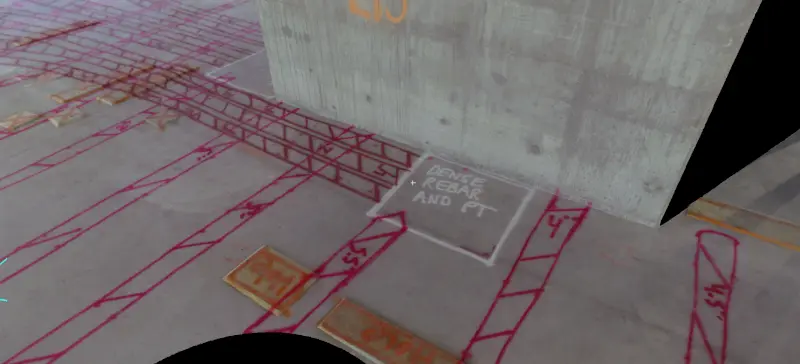
During concrete scanning, ground penetrating radar (GPR) equipment locates the exact position and orientation of objects embedded in concrete, including post tension cables, rebar, utilities, conduits, and pipes. GPR can also assess concrete thickness and detect probable voids. During concrete scanning, the locations and depths of the encased elements, concrete thickness and potential voids are precisely marked on the concrete using paint, marker, crayon, or tape.
What Objects Can Be Located in Concrete?
- Utilities – Locating utilities, conduits, and pipes running underneath the reinforcement of concrete prevents construction teams from damaging utilities and avoiding electrical shock or life-threatening injuries.
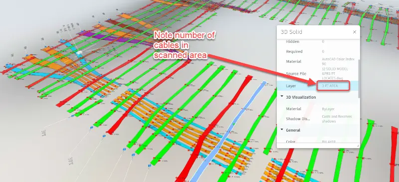
- Post Tension (PT) Cables – Locating post tension cables prior to construction or renovation allows workers to avoid cutting them, maintaining their safety and the integrity of the structure. Detailed information, such as the depth and quantity of PT tendons in each bundle can be determined.
- Rebar & Wire Mesh – Rebar and wire mesh patterns, position, and depth can be mapped for safe drilling, cutting, and coring. Scanning concrete can also determine if rebar deviates from the design plan.
Can You Permanently Document the Project Site?
Once objects are scanned and located in concrete, the findings can permanently be documented with 3D photogrammetry. A LiDAR camera delivers digital twins and high-resolution images of project sites. This method of reality capture offers many benefits from design planning to construction documentation. Photogrammetry offers these benefits:
- Delivers up-to-date as-builts for architects and designers to conceptualize designs and collaborate with a detailed understanding of the space
- Documents underground utilities and slab reinforcements during the critical period between inspection and coverup
- Provides precise concrete layouts, arming construction teams with critical information when preparing to cut, core, or drill into a structure
- Concrete scan data can help to analyze the structural integrity of existing buildings
- Aids plans for tenant build out, for example, data can help plan to demolish existing walls or construct new ones, and make modifications to electrical, HVAC, or plumbing systems
- Verify if construction is being performed to standards and according to design. This lowers the amount of change orders and delays due to error. For example, it’s easier to fix electrical and plumbing issues before putting up drywall
- Offers critical maintenance information once the building is complete, saving valuable time and money for the building owner
- Allow building operators to maintain inventory of equipment and assets
- Capture photos & 3D scans to document building progress
- Ensure a successful handoff from construction to facilities management
What is Photogrammetry?
Photogrammetry is the process of taking many photographs of a project site from a variety of angles and stitching them together to create a 3D model. Both 2D and 3D data can be extracted from an image and, by overlapping photos of the building or space, a 3D digital model can be created. Photogrammetry provides realistic 3D models because the photographs translate to great materials and textures. This delivers accurate digital twins.
GPRS uses 3D photogrammetry to capture both indoor and outdoor project sites. The technology we utilize delivers 20-millimeters accuracy within a 33' range and a maximum 328' scanning range. 100,000 data points are collected per second, and scans are completed in under 20 seconds per sweep. A custom 30-megapixel sensor and 12-element camera lens produces 134-megapixel photos, downloadable in a JPG format.
3D photogrammetry allows architecture, engineering, and construction professionals to utilize 3D virtual tours, plus clients can export schematic floor plans, CAD & BIM assets, and a E57 point cloud file for additional project work.
How Can Photogrammetry Help Your Construction Project?
Photogrammetry is a great tool for construction documentation. Not only can 3D photogrammetry capture concrete and utility markings, but it can also capture the structural and architectural elements, and building systems like electrical, mechanical, plumbing, and fire protection systems. These are some of the ways in which photogrammetry can help your construction project:
- Take a virtual tour of the project site
- Locate important site features and take measurements and dimensions of the space
- Export point clouds, floor plans, and reflected ceiling plans to CAD or BIM programs such as AutoCAD and Revit
- Tag the 3D space to create virtual punch lists and operation manuals. Add a short description and an external link with detailed information
- Add notes to specific spots in the virtual tour. Reduce friction and time to resolution by communicating to stakeholders exactly where the problem is
What Features Does Photogrammetry Offer?
Photogrammetry is useful for organizations responsible for design, construction, project management, acquisitions, and leasing. The following construction tools can be created from photogrammetry:
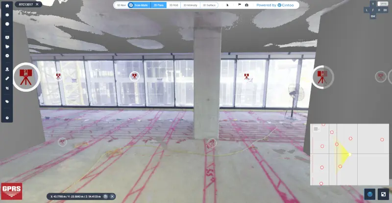
3D Virtual Tour is a collection of 360° panoramic rotating images, “stitched” together to form a full, 360° view of a location. The 3D virtual tour lets your team tour the location, manage issues, assign tasks, update workflows, add digital notes, and share pictures and videos with the project team. The virtual tour can be viewed through desktop computers, laptops, tablets, and mobile devices.
Schematic Floor Plans can be created, delivering each floor as a separate .PNG and .SVG file. A one-page .PDF can be created that combines all floors. Floor plans can be created for spaces that are 25,000 square feet or smaller. If you have a space larger than 25,000 square feet, you have the option to split it into smaller spaces and order a floor plan for each smaller space. The floor plans contain:
- Individual room measurements
- Illustrations of property features
- Total floor area calculation
CAD & BIM Assets can be downloaded as a ZIP file and imported into a third-party program like 3ds Max, ReCap, Revit, or AutoCAD. These assets are useful for architects, engineers, and construction professionals who want to perform additional work on 2D drawings or 3D model in a third-party program. CAD/BIM assets include:
- Colorized point cloud (.XYZ)
- Reflected ceiling plan (.JPG & .PDF)
- High-resolution floor plan (.JPG & .PDF)
- 3D mesh file (.OBJ), including the necessary texture map image files (.JPG)
The E57 File can be downloaded for architects, MEP engineers, general contractors, mechanical engineers, electrical engineers, BIM managers, VDC managers, and other construction professionals who need a high density point cloud. It contains the point cloud data, pano images, and metadata from each scan location. It's vendor-neutral and can be imported into a wide range of applications, such as Autodesk, Leica, and Cintoo Cloud. The E57 has more than 10 times the detail in point cloud density compared with the .XYZ file in the CAD & BIM asset bundle.
Building Information Management (BIM) Files allow architects, engineers, and construction professionals to import Building Information Management (BIM) files into Autodesk Revit software as an .RVT file, .IFC file, and .DWG files for floor plans and reflected ceiling plans. This feature is useful for organizations responsible for design, construction, project management, acquisitions, and leasing.
The GPRS Difference
Scanning and documentation are a critical part of any construction project. GPRS has more than 22 years’ experience and a 99.8% accuracy rating in concrete scanning and utility locating on more than 500,000 jobs. No other company has the ability to locate, mark, scan, map, and model a project site with the accuracy and detail as GPRS.
Each member of GPRS’ elite team of over 500 Project Managers has completed the industry-leading Subsurface Investigation Methodology (SIM) program. This program defines protocols for underground utility locating and concrete scanning that far exceed the industry norm.
We are so confident in our SIM-trained Project Managers that we introduced the Green Box Guarantee, which states that when GPRS places a Green Box within a layout before the crew anchors or cores concrete, they guarantee that the area will be free of obstructions.
GPRS Intelligently Visualizes the Built World™ above and below ground as the leading provider of accurate utility locating, concrete scanning & imaging, 3D laser scanning, video pipe inspection, leak detection, and mapping & modeling solutions for the construction, architecture, and engineering industries.
Once scanning is complete, GPRS offers a wide range of LiDAR, photogrammetry, and visualization services. We work closely with each client to define the project scope and use the right tools to achieve the accuracy, point clouds, 2D drawings, and 3D models needed to successfully complete each project. GPRS’s team of in-house engineers, architects and CAD technicians produces custom maps and models for your project.
What can we help you visualize?
How Can I Learn More About Concrete Safety?
GPRS Concrete Sawing & Drilling Safety Week (CSDSW) is an annual event designed to help job sites become safer. From January 29 – February 2, 2024 GPRS safety experts will travel the country to give complimentary Concrete Sawing and Drilling Safety Week presentations. These free educational seminars include breakfast or lunch and are focused on mitigating the risks of working with and around concrete.
Frequently Asked Questions?
What is 3D photogrammetry?
Photogrammetry is a technique for obtaining reliable data from real-world objects in the their natural state by creating 3D models from photographs. 2D and 3D data is extracted from an image and, thanks to overlapping photos of the object, building or terrain, is converted into a 3D digital model.
How is photogrammetry utilized in construction?
Photogrammetry is a new construction technology to capture a space in 3D. This comprehensive platform transforms building spaces into digital twin models. Users can view a building layout without being there.
What is a point cloud?
A point cloud is a 3D description of spatial data consisting of geometric points in space, as measured by capture devices. These points typically represent the 3D shape of a physical object. Each point position has its set of Cartesian coordinates (X, Y, Z). Point clouds are most commonly used to capture the existing (as-built) conditions of a structure. Point cloud data is commonly used to extract analysis from these structures, and to import into 3D design and BIM software workflows.
Does photogrammetry integrate with Revit?
Yes. Clients can directly import assets into Autodesk Revit using our free add-in for Revit. This allows photogrammetry data to be directly imported into Revit without downloading very large assets to disk and then going through Autodesk Recap first. The add-in accesses the Recap SDK (software development kit) to convert the files in the background and import them directly into Revit.