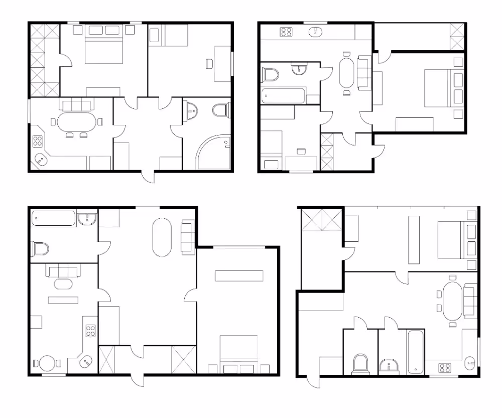
A plan view is an invaluable asset to have in various stages of construction, maintenance, and operation.
Also known as a top view, floor plan, or bird’s-eye view, it represents a facility or project as if viewed from above, offering a comprehensive layout of its spatial arrangements. This perspective is invaluable in various stages of construction, maintenance, and operation.
To obtain an accurate plan view of a facility or project, it’s vital to incorporate key methodologies and technologies such as 3D laser scanning, 3D photogrammetry, and utility locating.
Understanding the Importance of Plan Views
Plan views are integral to infrastructure mapping because they provide a clear, detailed representation of a site’s layout. This visual aid is essential for:
- Design and Planning: Helping architects and engineers visualize spatial relationships and align new construction with existing structures
- As-Built Documentation: Ensuring accurate records of the completed project for future reference and maintenance
- Existing Conditions Documentation: Capturing the current state of a facility for renovations or expansions
- Utility Locating: Identifying underground utilities to prevent damage during excavation and construction
How to Obtain a Plan View
Initial Site Assessment
The first step in obtaining a plan view is a thorough site assessment. This involves:
- Site Visits: Conducting physical inspections to understand the site's layout, topography, and key features
- Document Review: Examining existing documentation, such as blueprints and previous surveys, to gather preliminary information
Choosing the Right Technology
Different technologies are available to create detailed and accurate plan views. Selecting the right one depends on the project’s complexity, size, and specific requirements.
3D Laser Scanning
3D laser scanning is a highly accurate method for capturing the geometry of a site. It uses laser beams to measure distances between the scanner and the surfaces of objects, generating a precise 3D model.
Advantages: Provides high-resolution data, captures intricate details, and is efficient for large or complex facilities.
Process: Set up the scanner at multiple locations around the site to cover all angles. The scanner emits laser pulses, which bounce back from surfaces to create a dense point cloud representing the site’s geometry.
Drone Photogrammetry
Drones equipped with cameras can capture aerial images of a site, which are then processed to create a detailed map.
Advantages: Ideal for large outdoor sites, provides a comprehensive overview quickly, and can cover inaccessible areas.
Process: Plan the drone’s flight path to ensure complete coverage. After the flight, use photogrammetry software to stitch the images together and generate a 3D model or orthomosaic map.
Data Collection
Using the chosen technology, collect the necessary data:
- For 3D Laser Scanning: Position the scanner at various points around the site. Ensure that overlapping scans are taken to cover all areas and eliminate blind spots. The result is a point cloud data set
- For Drone Photogrammetry: Conduct the drone flight as per the planned path, ensuring that the camera captures overlapping images. Post-processing these images will yield a detailed 3D model
Data Processing and Analysis
Once data collection is complete, the next step is processing and analyzing the data to create a plan view.
- Point Cloud Processing: For 3D laser scanning, use software to convert the point cloud into a usable format, such as a 2D floor plan or a 3D model. Tools like AutoCAD or Revit can be employed to extract specific views and dimensions
- Image Stitching: For 3D and drone photogrammetry, employ photogrammetry software to combine images into a coherent map. This involves registration: the process of aligning and merging the images based on their GPS coordinates and visual overlap
Creating the Plan View
With the processed data, you can now create the plan view:
- 2D Drawings: Convert the 3D data into 2D plan views using CAD software. This involves drawing lines and shapes to represent walls, windows, doors, and other features from the top-down perspective
- Overlaying Utility Data: If utility locating is part of the project, integrate the data from ground-penetrating radar (GPR) or electromagnetic (EM) locating tools. This will highlight the position of underground utilities like pipes and cables
Verification and Validation
Before finalizing the plan view, it’s crucial to verify and validate the accuracy of the data:
- **Field Verification**: Conduct on-site checks to ensure that the plan view matches the actual conditions. This may involve measuring distances and comparing them with the data.
- **Client Review**: Share the plan view with stakeholders or clients for feedback and approval. Incorporate any necessary adjustments to meet their requirements.
Final Documentation
Once the plan view is verified and validated, compile the final documentation:
- As-Built Documentation: Prepare detailed drawings and records that accurately represent the completed facility. This documentation is essential for future maintenance, renovations, and compliance with regulatory requirements
- Existing Conditions Documentation: For projects focusing on renovations or expansions, ensure that the plan view accurately reflects the current state of the facility
Applications of Plan Views
Plan views have wide-ranging applications across various industries, including:
- Construction: Facilitating the design and coordination of new buildings and infrastructure
- Utilities and Infrastructure: Mapping underground utilities and ensuring safe excavation practices
- Facility Management: Assisting in the maintenance and operational planning of large facilities
- Historic Preservation: Documenting heritage sites and ensuring their accurate restoration
- Emergency Response Planning: Plan views are invaluable in emergency response planning as they provide detailed, overhead representations of buildings and areas, enabling responders to quickly understand layouts, identify critical access points, and strategize efficient evacuation and intervention routes
- Real Estate Leasing and Sales: Plan views play a crucial role in real estate leasing and sales by offering clear, bird’s-eye illustrations of property layouts, which help potential tenants and buyers visualize space utilization, assess room dimensions, and make informed decisions about the functionality and suitability of the property for their needs
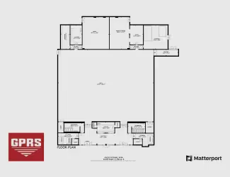
GPRS FLRPLN: Accurate Existing Condition Documentation
Through our FLRPLN service, GPRS converts photogrammetry into 2D floorplan views, delivered digitally and shareable via SiteMap® (patent pending) so that they can be downloaded, saved, and shared to any laptop, tablet, or smartphone and are accessible 24/7.
FLRPLN provides fast 2D CAD plan views of buildings, facilities, and sites, documenting existing conditions to expedite planning and improve communication with clients and contractors. Reference valuable property information, such as layout, dimensions, and details of rooms, walls, doors, windows, architectural, structural, and MEP features to communicate design intent, coordinate construction activities, mitigate risk, develop emergency plans and safety procedures, and more.
From skyscrapers to sewer lines, GPRS Intelligently Visualizes The Built World® to keep your projects on time, on budget, and safe.
What can we help you visualize? Click below to schedule a service or request a quote today!