

.svg)
In 2017, a vacant site in one of the largest cities in the U.S. broke-ground to begin a mixed-use redevelopment project, containing event, hotel, meeting, office, parking, residential, restaurant, and retail space. The new building is planned to be 680 feet tall, encompass 1.5 million gross square feet, and have 49 floors.
GPRS’ client, a general contractor, was completing fit and finish design plans for a hotel, which will reside on 12 floors. The estimated cost for the hotel build-out is $84.7 million.
Approximately 12,500 sq. ft. of reinforced concrete foundations were poured for each floor of the high-rise. The GC had the challenge of planning and coordinating the MEP and HVAC connections between the hotel guest rooms after the concrete was poured. This required precise planning and engineering of the mechanical, electrical, plumbing, and fire protection designs.
The post tension cable system created many obstructions to work through for below-grade MEP and HVAC installation. That’s why the general contractor hired GPRS to locate and mark the full post tension cable layout, so they could design the building fit-out, resolve clash detections, and coordinate a trade schedule.

How Do You Determine Post Tension Cable Layout?
The best way to determine post tension cable location and depth is with ground penetrating radar (GPR) and 3D laser scanning technology.
GPR technology is a non-destructive concrete scanning detection and imaging method that sends a radio wave from a receiver into a concrete structure. The wave will “bounce” off any material it encounters. Those bounces are then displayed in a reading as a hyperbola, and a professional concrete scanning technician can interpret that data to tell you what was found and exactly where it is located. Post tension cable layouts must be traced in short distances to reveal the slope.
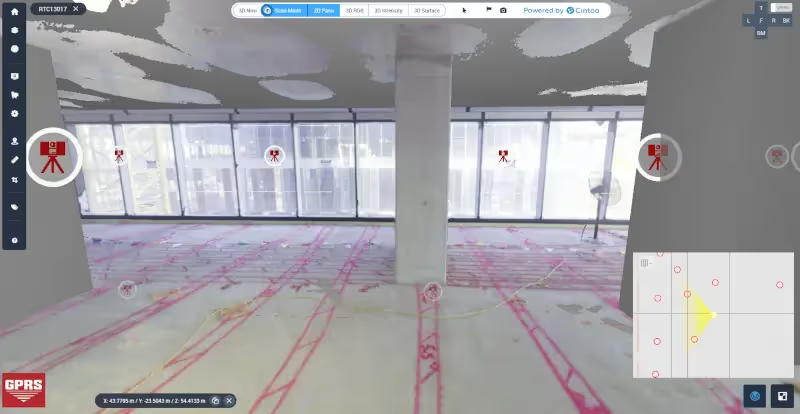
3D laser scanning captures an accurate map of the site pre-pour and after field markings are complete, in the form of a point cloud, where every point of the scan is converted to a pixel with a known x, y, and z coordinate.
GPRS had a comprehensive plan to capture the post tension cable system layout for the general contractor. A team of GPRS Project Managers 3D laser scanned the slabs pre-pour to document the post tension cable system in the form of a point cloud. The concrete was poured for each floor. Then, the team located and marked the post-tension cable system with GPR technology, including the location, number of cables, and depth directly on the slab and ceiling. 3D laser scanning was completed a second time to collect the concrete field markings on the slab.
From the scan data, the GPRS Mapping and Modeling team created 2D plan sheets and 2D floor elevation contour maps to add more accuracy to the depth of cover that was field marked. The data was also used to create a 3D BIM model and virtual tour of the site pre and post-pour.

Safe Cutting, Coring & Drilling for MEP and HVAC Installations
The 2D CAD drawings and 3D BIM model provided the general contractor with precise data for virtual design and construction. This permanent record of the post-tension cable system layout was used to complete fit and finish design plans for the building.
Accurate post tension layout will ensure safe cutting, coring, and drilling during the MEP and HVAC installations. Mapping the support grid in concrete slabs facilitates design and minimizes the risk of injuries and delays.
What is a Post Tension Cable System?
Post-tensioned systems consist of a series of high-strength steel cables embedded within concrete slabs that, once stressed, support the loads imposed on the slabs. The cables are commonly called “tendons.”
Post-tensioned cable systems reinforce concrete, allowing structures to require fewer beams, longer clear spans, more slender elements, and thinner slabs. This helps to reduce the amount of concrete required for construction, also reducing the weight and height of the building. Lower building weight and height can contribute to savings in terms of facade and mechanical system costs. There will also be a lesser load on the foundation.
Post tension cable location, spacing, and depth are determined by an engineer, and are specific to each project.
Drilling, cutting, or coring into a post-tension slab can be dangerous. It is important to avoid hitting the cables when cutting or drilling for construction or renovation. Each tendon pulls 24,000 to 33,000 lbs. of pressure. Damaging a cable when cutting, coring, or drilling into a slab can cause a tendon to burst with enough force to cause severe injury or death, and impact the structural integrity of the slab.
This is why it is important to locate post-tension cable systems when finishing or repairing buildings or structures. An accurate layout of post-tension cables protects tendons from damage, prevents injury and mistakes, and protects the integrity of the building.
Why GPRS? The GPRS Difference
Each member of GPRS’ elite team of over 500 Project Managers has completed the industry-leading Subsurface Investigation Methodology (SIM) program. This program defines protocols for concrete scanning that far exceed the industry norm.
The SIM program consists of 80 hours of hands-on classroom training and 320 hours of mentorship in the field to ensure Project Managers’ competence in utilizing GPR equipment, EM locators, and 3D laser scanners.
SIM allows GPRS Project Managers to clear dozens of cutting/coring areas daily with an exemplary level of accuracy. GPRS is so confident in our SIM-trained Project Managers that we provide a Green Box Guarantee, which states that when GPRS places a Green Box within a layout before the crew anchors or cores concrete, we guarantee that the area will be free of obstructions.
GPRS is the nation’s leading provider of utility locating, concrete scanning and imaging, 3D laser scanning, video pipe inspection, leak detection, drone photogrammetry, and mapping & modeling services for the construction, architecture, and engineering industries. Since 2001, GPRS has led the industry, providing accurate data and outstanding service to improve planning and communication and mitigate risk for your team.
What can we help you visualize?

Frequently Asked Questions
What is core drilling?
Core drilling creates holes in concrete that make it easy for pipes, utility lines, and other objects to pass through to the other side, a common practice for plumbing, electrical, and HVAC contractors.
How much does it cost to replace a post-tension cable?
Replacing a single post-tension cable costs $10,000 - $20,000.
What does HVAC mean?
HVAC is an acronym that stands for Heating, Ventilation, and Air Conditioning. The term HVAC is used to describe a complete comfort system that can be used to heat and cool your building, as well as provide improved indoor air quality.