

.svg)

Highlights
THE BOTTOM LINE
GPRS’ detailed 2D CAD drawings and 3D BIM model allow for safe cutting, coring & drilling for building-wide MEP and HVAC installations.
INDUSTRY
Construction
SERVICE
Concrete Scanning, 3D Laser Scanning & 3D BIM Modeling
LOCATION
Detroit, Michigan
PM Insight
Deliverables
PROJECT APPLICATION
Concrete scanning services will locate critical targets like post tension cables, rebar, conduits, voids, and more to help keep your project on time, on budget, and safe. 3D laser scanning captures concrete markings with 2-4mm accuracy for GPRS to transform into custom 2D CAD drawings and 3D BIM models.
ASK
Task
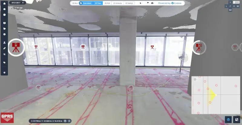
GPRS located and marked the full post-tension cable system layout for 12 floors of a 49-floor building, with approximately 12,500 sq. ft. of concrete on each floor. After concrete scanning was completed with ground penetrating radar technology, GPRS 3D laser scanned each floor to produce 2D CAD drawings and a 3D BIM model for virtual design and construction. The architect received a permanent record of the post-tension cable layout to complete fit and finish design plans for the building.
PROBLEM
- Post-tension cable location, spacing, and depth are determined by an engineer, are specific to each project, and must be traced in short distances to reveal the slope.
- Each tendon pulls 24,000 to 33,000 lbs. of pressure. Damaging a cable when cutting, coring, or drilling into a slab can cause a tendon to burst with enough force to cause severe injury or death, and impact the structural integrity of the slab.
- Replacing a single post-tension cable costs $10,000 - $20,000.
Solution
- Experienced Project Managers used ground penetrating radar (GPR) technology to locate and mark the precise details of each concrete reinforcement, documenting the location, number of cables, and depth directly on the slab and ceiling.
- After the post-tension layout was complete, each floor was 3D laser scanned to capture the field markings. That data was used to create a virtual tour, 2D CAD drawings (PT site layout and floor contours,) and a complete 3D BIM model of the site.
- The captured point cloud data was aligned to survey control, then to the client’s design model, further ensuring the accuracy of the data.
Benefits
- GPRS has a verified 99.8% accuracy rate for concrete scanning, backed by our Green Box Guarantee. Laser scanning is accurate within 2-4mm.
- An accurate layout of post-tension cables protects tendons from damage, prevents injury and mistakes, and protects the integrity of the building.
- 2D plan sheets and a 2D floor contour map documenting the actual floor elevation added even more accuracy to the depth of cover that is field marked.
- The 3D BIM model provided the architect data to plan fit and finish designs and coordinate with contractors and MEP trades before build-out.
CASE STUDY GALLERY


.avif)


.avif)
