industry insights
Featured Articles
Is Utility Mapping Worth the Cost?
Why Do You Need Updated As-Builts on Your Next Project?
industry insights
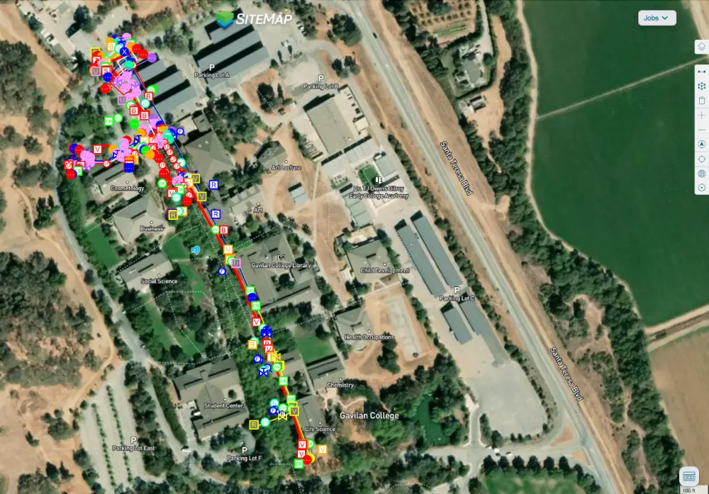
How GPRS Utility Locating & SiteMap Captured Accurate Data for 150-Acre Community College
GPRS provided accurate utility locating and mapping services to help a contractor stay on time, on budget, and safe while installing water lines throughout a 150-acre community college.
GPRS Project Manager James Turrentine was contacted by Arizona Pipeline Co., which was installing the water lines across Gavilan College in Gilroy, California.

A Brief History of Gavilan College
The school was originally established in 1919 as San Benito County Junior College, with instruction offered at Hollister High School. It operated under this name until 1963, when a new community college district was drawn that included both San Benito and southern Santa Clara Counties. A local bond passed in 1966 which provided the funds necessary to construct the college’s current campus at Santa Teresa Boulevard in Gilroy.
Like many historic campuses across the country, Gavilan had no accurate existing as-builts to provide to Arizona Pipeline as the latter was preparing to trench to install the new water lines.
How GPRS Located the Water Line and Other Utilities
Arizona first contacted GPRS to locate a single existing water line on the campus.
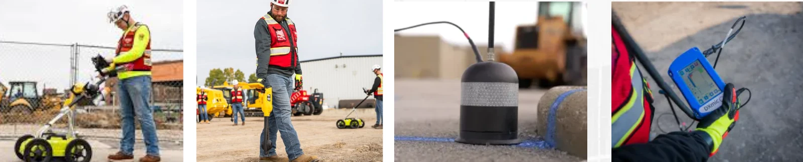
GPRS provides precision utility locating services utilizing ground penetrating radar (GPR) and electromagnetic (EM) locating. GPR scanners emit radio waves into a surface or underground, then detect the interactions between the signals and any buried objects such as conduit, pipelines, or underground storage tanks (USTs). These interactions are displayed as a series of hyperbolas on a GPR readout, and GPRS Project Managers interpret this data to provide accurate location and depth data for these obstructions.
EM locators detect the electromagnetic signals radiating from metallic buried utilities, and as such are a perfect complement to GPR scanning. These signals can be created by the locator’s transmitter applying current to the pipe, or from current flow in a live electrical cable. They can also result from a conductive pipe acting as an antenna and re-radiating signals from stray electrical fields (detected by the EM locator functioning in Power Mode) and communications transmissions (Radio Mode).
Signals are created by the current flowing from the transmitter which travels along the conductor (line/cable/pipe) and back to the transmitter. The current typically uses a ground to complete the current. A ground stake is used to complete the circuit through the ground.
By utilizing both GPR scanning and EM locating, Turrentine was able to locate the buried water line for Arizona Pipeline. Not only did he mark out the location of the utility on the ground using flags and paint, but he also uploaded this data into SiteMap® (patent pending), GPRS’ intuitive, interactive utility mapping software application.
Securely accessible 24/7 from any computer, tablet or smartphone, SiteMap is the single source of truth a facility manager or general contractor needs to ensure their team can plan, design, manage, dig, and ultimately build better. It eliminates the mistakes caused by inaccurate/incomplete as-built documents and replaces them with the peace of mind that comes with knowing where all buried utilities are located – and therefore knowing where you can and can’t safely dig.
How a Water Line Locate Became a Full Site Utility Survey
When Turrentine showed his site contract with Arizona Pipeline the utility locating data he obtained and uploaded into SiteMap, the contact was so impressed that he asked GPRS to locate and map all the buried infrastructure across Gavilan College’s entire campus.
“[Turrentine] showed them in SiteMap their scope of work that they called us out there to do,” said GPRS Area Manager Jake Wright. “And [the client] said ‘Oh wow, we actually have hundreds of [utility] trenches we need to do. Could we do the whole campus like that?’ And Turrentine said ‘Yeah, totally.’”
While every GPRS customer receives complimentary SiteMap Personal access to view the data we collect for them, the platform can be tailored to meet your individual needs. Arizona Pipeline received SiteMap Project access so that their entire team would have access to the accurate, field-verified data collected on-site by Turrentine throughout their project’s lifecycle.
From college campuses to skyscrapers, GPRS Intelligently Visualizes The Built World® to keep your projects on time, on budget, and safe.
What can we help you visualize?
Frequently Asked Questions
What informational output do I receive when I hire GPRS to conduct a utility locate?
Our Project Managers flag and paint our findings directly on the surface. This method of communication is the most accurate form of marking when excavation is expected to commence within a few days of service.
GPRS also uses a global positioning system (GPS) to collect data points of findings. We use this data to generate a plan, KMZ file, satellite overlay, or CAD file to permanently preserve results for future use. And all this accurate-field-verified data is uploaded into SiteMap®, so you and your team have secure, 24/7 access.
GPRS does not provide land surveying services. If you need land surveying services, please contact a professional land surveyor.
Please contact us to discuss the pricing and marking options your project may require.
Can ground penetrating radar find PVC piping and other non-conductive utilities?
GPR scanning is exceptionally effective at locating all types of subsurface materials. There are times when PVC pipes do not provide an adequate signal to ground penetrating radar equipment and can’t be properly located by traditional methods. However, GPRS Project Managers are expertly trained at multiple methods of utility locating.
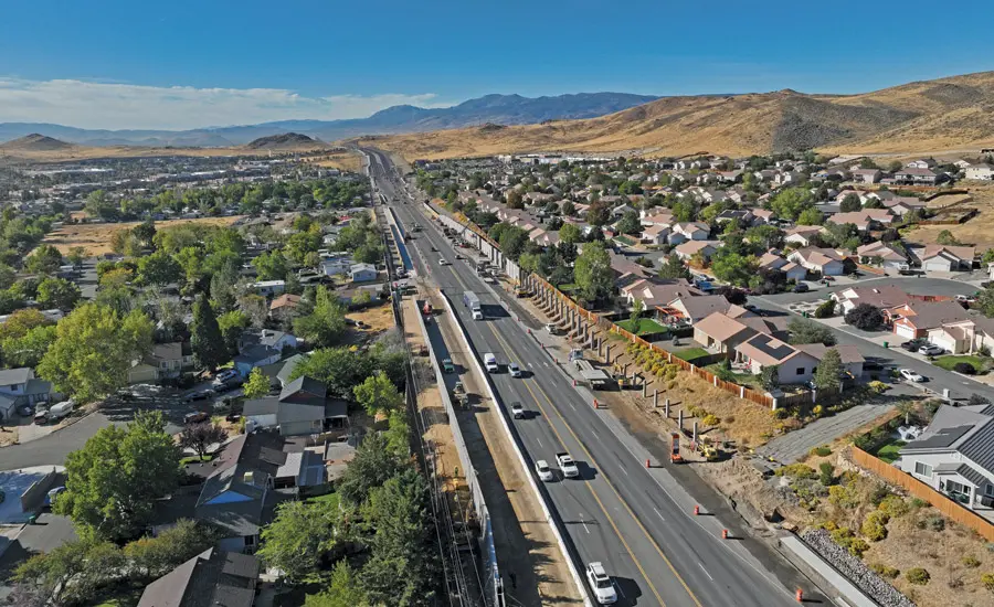
High-Pressure Water Line Nearly Derails $66M Road Project
A $66-million road project near Reno, Nevada hit a major speedbump when it was discovered that a high-pressure water line ran right through the project area.
Watsonville, California-based Granite Construction is the general contractor on the first phase of the six-phase Pyramid Highway Project, which is rebuilding and widening about 2.5 miles of the arterial road that serves 50,000 vehicles daily.
Expected to be completed this summer, this project will see much of the road expand from four to six lanes, along with the addition of bike lanes, sidewalks curbs, gutters, a 10-ft shared-use path on one side of the road, smart traffic signals, sound walls, enhanced lighting, landscaping, and improved drainage infrastructure.
“These upgrades are designed to improve traffic flow, safety and accessibility for all users,” Nanette Maxwell, senior project manager for NDOT, the lead agency on the project, told Engineering News-Record. “This project will not only reduce traffic congestion and travel times, but it will also generate significant crash-cost savings for vehicles, bicyclists and pedestrians” because the improvements are expected to reduce accidents.
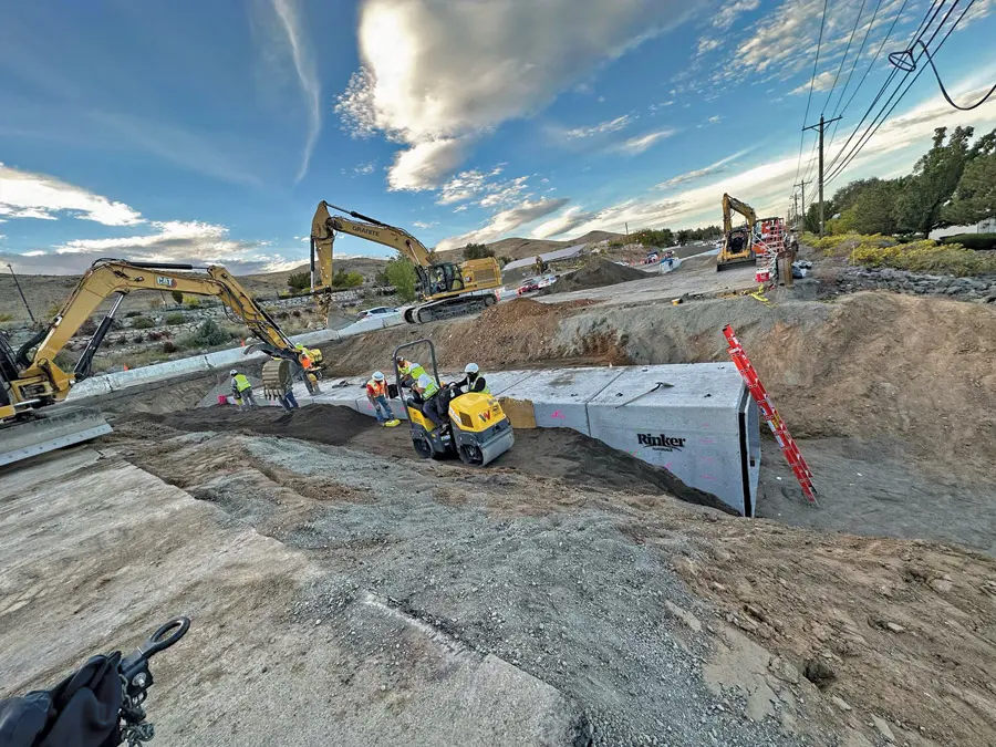
According to ENR, the local water utility notified the construction team about the previously unidentified water line running through the project area. The line serves the nearby community of Spanish Springs, and the water utility told the construction team that it needed to be at least 2 ft below ground.
A subsequent review of subsurface utility exploration data revealed a small section of the pipe would have less than 2 ft of cover.
Revealing too much of the high-pressure line risked compromising its integrity, and shutting off the water was not feasible. To mitigate the risk, crews advanced in 50-foot sections, excavating and clearing surface material down to the subgrade. The exposed area was then graded and compacted. A temporary gravel layer was placed over the pipe for protection, which will later be replaced with an aggregate base during final roadway construction.
“Meetings were held between NDOT, Granite and the local water authority to develop a work plan allowing the contractor to continue working,” Aaron Lobato, roadway design project coordinator at NDOT, told ENR.
Amanda Callegari, commission engineering manager, told the publication that the collaborative elements of the project – including the real-time multiagency cooperation necessary to overcome the water line problem – show how important Pyramid Highway is to Reno’s present and future. The highway – designated State Route 445 – is an important commuter route for the area’s growing population, with more than 90% of the 40,000 people who live within two miles of the project working outside the area.
“This project holds regional significance and will provide meaningful benefits to the growing community,” Callegari said. “To ensure its successful delivery, the [commission] and NDOT have joined forces to implement these vital improvements.”
How Accurate Utility Locating Protects Your Infrastructure Projects
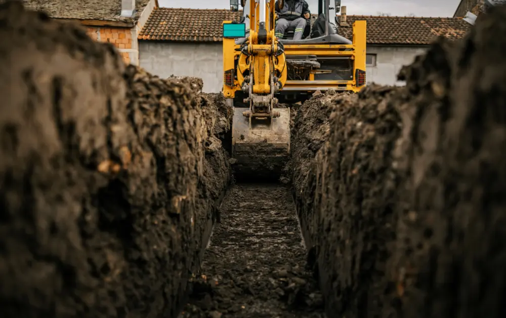
Whether it’s a high-pressure water line, an electrical conduit, or a gas main, striking a buried utility while excavating can have costly consequences.
Subsurface damage endangers the lives of your workers and residents of the surrounding community. And the downtime and cost of repairing the damage can decimate your schedule and budget.
Calling your local 811 center should be your first step whenever you’re planning an excavation. Federal law requires you contact 811 to receive the approximate location of all registered utilities within your project area prior to breaking ground. Registered utilities can consist of both private and public lines, but it’s important to remember that not all utilities are registered with 811.
GPRS’ professional utility locating services compliment your 811 locate by providing you with accurate and complete data about the buried infrastructure on your job site. Utilizing ground penetrating radar (GPR), electromagnetic (EM) locating, and other non-destructive subsurface investigation technologies, we identify where you can and can’t safely dig.
All this data is at your fingertips 24/7 thanks to SiteMap® (patent pending), GPRS’ interactive utility mapping software application that provides accurate existing conditions documentation to protect your assets and people.
Securely accessible from any computer, tablet or smartphone, SiteMap enables seamless communication between you and your project team. You’ll be able to plan, design, manage, dig, and ultimately build better.
From skyscrapers to sewer lines, GPRS Intelligently Visualizes The Built World® to keep your projects on time, on budget, and safe.
What can we help you visualize?
Frequently Asked Questions
What do I get when I hire GPRS to conduct a utility locate?
Our Project Managers flag and paint our findings directly on the surface. This method of communication is the most accurate form of marking when excavation is expected to commence within a few days of service.
GPRS also uses a global positioning system (GPS) to collect data points of findings. We use this data to generate a plan, KMZ file, satellite overlay, or CAD file to permanently preserve results for future use. GPRS does not provide land surveying services. If you need land surveying services, please contact a professional land surveyor.
Please contact us to discuss the pricing and marking options your project may require.
What are the Benefits of Underground Utility Mapping?
Having an updated and accurate map of your subsurface infrastructure reduces accidents, budget overruns, change orders, and project downtime caused by dangerous and costly subsurface damage.
How does SiteMap® assist with Utility Mapping?
SiteMap®, powered by GPRS, is the industry-leading infrastructure management program. It is a single source of truth, housing the 99.8%+ accurate utility locating, concrete scanning, video pipe inspection, leak detection, and 3D laser scanning data our Project Managers collect on your job site. And the best part is you get a complimentary SiteMap Personal Subscription when GPRS performs a utility locate for you.
Does SiteMap Work with my Existing GIS Platform?
SiteMap allows for exporting of data to SHP, GeoJSON, GeoPackage, and DXF directly from any user’s account that either owns or has a job shared to their account. All these file formats can be imported and utilized by other GIS packages if manually imported by the user.
46% of Americans Will Dig Without Calling 811, Survey Finds
A survey conducted by the Common Ground Alliance (CGA) found that 46% of Americans plan to dig without contacting 811.
Released in observance of National Safe Digging Month in April, the CGA’s national survey found that 68% of Americans plan to tackle a do-it-yourself project involving digging within the next year, but 27.2 million of them will not contact 811 before digging.
Not only is this illegal – homeowners and contractors alike are required by law to contact their local 811 before breaking ground on any size of excavation project – it's also dangerous. Digging without knowing what’s below risks damaging buried utilities, disrupting service to nearby residences and businesses and endangering anyone in the vicinity of the excavation.
"Our survey found that 46% of Americans don't plan to notify 811 before digging, with most believing their project is too shallow to merit an 811 request,” said CGA President and CEO Sarah K. Magruder Lyle. “This misconception puts homeowners and their neighbors at risk of injury and utility service interruptions. The reality is that utility lines can be buried just inches below the surface, which is why everyone must contact 811 before every digging project—whether it's installing a patio or major construction."
To keep homeowners, families and communities safe, a few days before breaking ground, make a free request to have the approximate location of underground lines marked with flags or paint by calling 811 or visiting www.811beforeyoudig.com. This National Safe Digging Month, and all year long, take the following steps when planning a digging project:
- Always contact 811 a few days before digging, regardless of the depth or familiarity with the property
- Plan ahead. Make a free 811 request on Monday or Tuesday for work planned for an upcoming weekend, providing ample time for the approximate location of lines to be marked
- Confirm that all lines have been marked
- Consider moving the location of the project if it is near utility line markings
- If a contractor has been hired, confirm that the contractor has contacted 811. Don't allow work to begin if the lines aren't marked
Everyone who contacts 811 a few days before digging is connected to a local 811 center that collects the information and communicates it to local utility companies. Professional locators will then visit the dig site to mark the approximate location of underground utility lines with spray paint, flags or both. Once a site has been accurately marked, it is safe to begin digging around the marked areas.
How GPRS Compliments Your 811 Locate
While you should always contact your local 811 One Call Center prior to digging, you should also hire a professional private utility locating company to locate and map all buried utilities in your intended dig area before you put a shovel or bucket in the ground.
GPRS is the nation’s largest professional private utility locating company. We’ve achieved and maintain a 99.8%+ accuracy rate when locating buried utilities, allowing us to compliment 811 services and the tools that support them.
Utilizing ground penetrating radar (GPR) scanners and electromagnetic (EM) locators, our SIM-certified Project Managers collect the accurate, complete data you need to stay on time, on budget, and safe. And this information is always at you and your team’s fingertips thanks to SiteMap®, our facility & project management application that provides existing conditions documentation to protect your assets and people.
What can we help you visualize?
FREQUENTLY ASKED QUESTIONS
What type of informational output is provided when GPRS conducts a utility locate?
GPRS Project Managers flag and paint their findings directly on the surface. This method of communication is the most accurate form of marking when excavation is expected to commence within a few days of service.
We also use a global positioning system (GPS) to collect data points of findings. We use this data to generate a plan, KMZ file, satellite overlay, or CAD file to permanently preserve results for future use. GPRS does not provide land surveying services. If you need land surveying services, please contact a professional land surveyor. Please contact us to discuss the pricing and marking options your project may require.
Can GPRS locate PVC piping and other non-conductive utilities?
GPR scanning is exceptionally effective at locating all types of subsurface materials. There are times when PVC pipes do not provide an adequate signal to ground penetrating radar equipment and can’t be properly located by traditional methods. However, GPRS Project Managers are expertly trained at multiple methods of utility locating.
Can GPR be used to verify known measurements?
We can use GPR to cross-check the measured depth and location of a located utility with existing as-built plans to verify the accuracy of plans.
GPRS Project Managers Donate Their Time to Locate Underground Electrical Lines for a Florida Charity
Late one evening, GPRS Project Manager Thomas Judge received a message from Kristopher Nickerson, a Senior Project Manager for Skanska. Judge had worked Skanska often, but he wasn’t expecting to hear about a job so late in the afternoon.
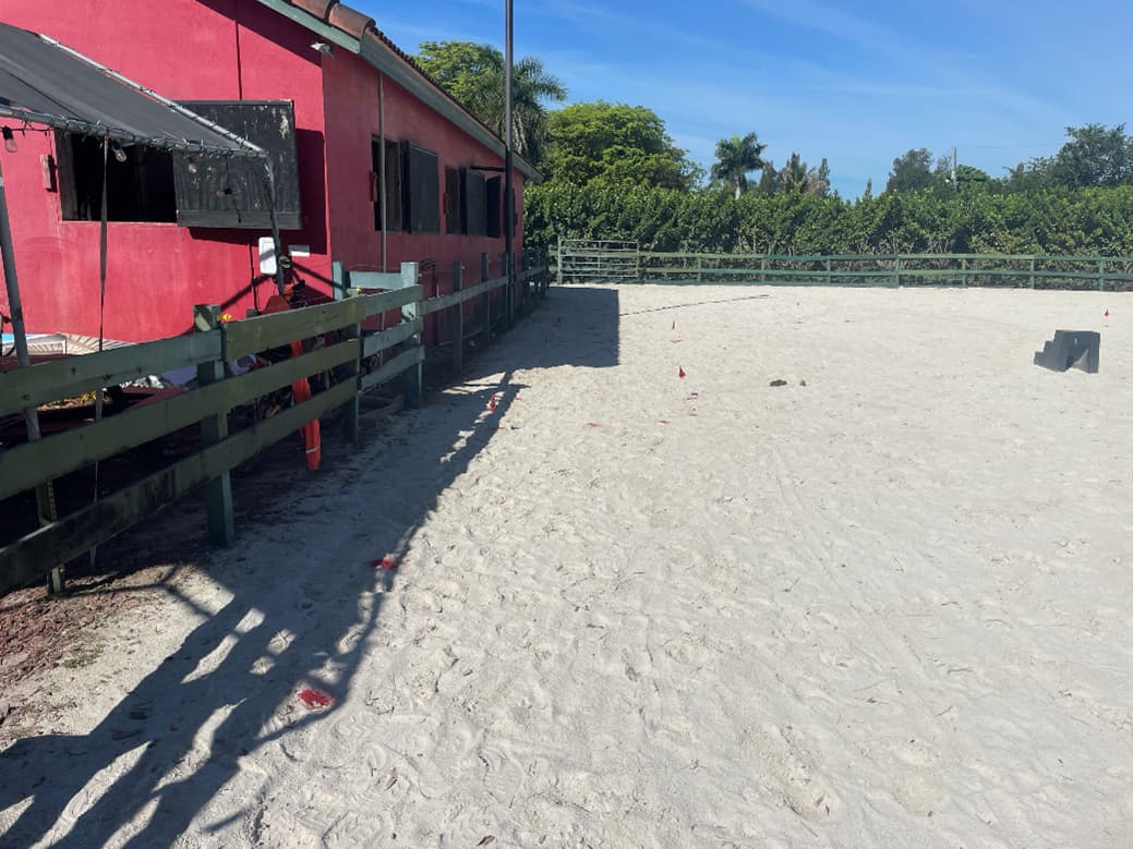
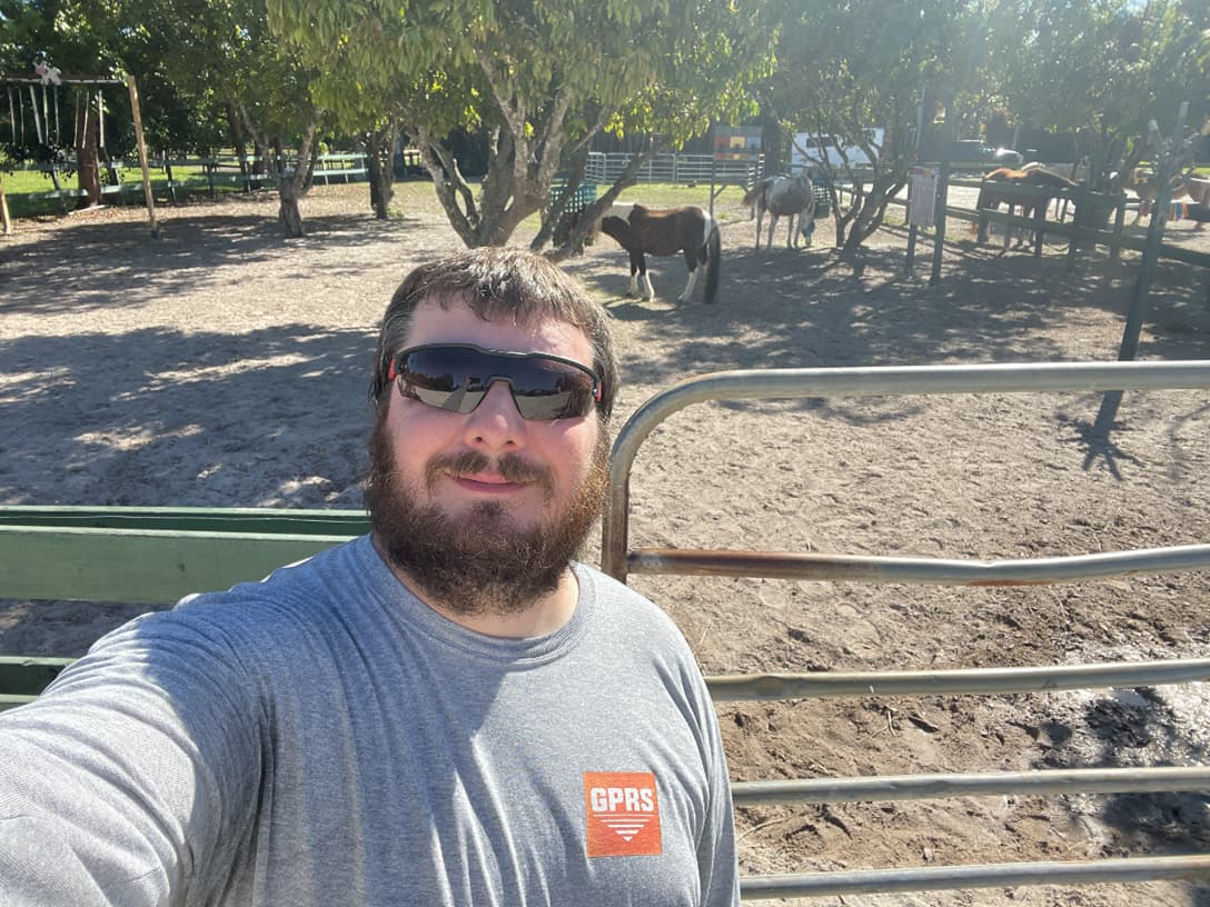
Nickerson had reached out asking for some help locating electrical lines for a charity in South Florida called the Bit-By-Bit Medical Therapeutic Riding Center. Bit-By-Bit is a charity that provides healing with the help of horses to special needs children and veterans. The accredited riding center provides speech, occupational, and physical therapies, while also aspiring to empower everyone they serve and transform their lives.
When their initial local utility locator had to bow out, the charity needed a back-up and they needed it immediately. Nickerson also made sure to inform Judge that Skanska was working free of charge for the charity, so Judge would be donating his time.
Judge didn’t hesitate to agree to the job and called fellow GPRS Project Manager Cameron Church, who also agreed to help.
“It was the night before when he sent out that message and I said, ‘Yeah, I'm clear,’” Church said. “Tomorrow, throw it on me first thing in the morning and let's get this done for them.”
Church, who is a veteran of the United States Air Force, was even more honored to be able to help once he learned the charity does work with veterans.
“Being a veteran of the Air Force myself, I knew this was a chance to give back,” Church said. “Let’s do it.”
The next morning, Judge and Church arrived at Bit-By-Bit Medical Therapeutic Riding Center. Upon their arrival, they performed a site walk to analyze the area while also having the opportunity to check out the majestic horses that have helped countless people in need. The job was simple: all they had to do was locate underground electrical lines so an area of the barn could be converted into an office space. However, there were some factors that made this job more interesting and potentially difficult.
“The whole area between that barn and where the utility pole was located at, where the power was coming off, that was all sand,” Church explained.
The vast majority of where Judge and Church would be scanning was in a sanded area that served as a corral and exercise space for the horses. GPRS Project Managers are trained to mark underground utilities with spray paint or flags that symbolize different utilities depending on the color. Marking the lines was going to be difficult as the markings could be easily altered by the horses and volunteers walking around the sanded areas.
Despite any challenges Judge and Church would have faced, their extensive training and experience allowed them to find the right solutions.
“It's sand. So with the horses riding around here, how do you want this marked?” Church pondered. “I can paint this, and I can flag it, but it's not going to take long for the marks to be completely gone. So then, they just reassured me that they would do what they could to make sure that the marks were going to stay there, and we took plenty of pictures before I left that day.”
GPRS’ SIM-certified Project Managers utilize Ground Penetrating Radar (GPR) and Electromagnetic (EM) locators to achieve 99.8% accurate utility scans and lower the risk of utility strikes at all stages of the project life cycle. Once the utilities are located, every GPRS customer receives their digitalized utility locates via SiteMap®, GPRS’ secure infrastructure and facility management software application.
After Church and Judge documented and marked their findings, they presented them to Bit-By-Bit who had a different idea of where these lines were located.
“We traced out the electric and it ended up being on the opposite end of their field from where they thought it was,” Church explained. “They knew it came off the [utility] pole and they knew it crossed over, but they thought it crossed over on the east side and it actually crossed over on the west. So, they were a little surprised by that.”
Without GPRS’ help, who knows how much time and resources would have been wasted looking in the wrong place for an electrical line?
Upon the completion of the utility scan and data delivery, Bit-By-Bit and Skanska were both appreciative of the time and effort both Judge and Church donated.
“I just know that Phil Nickerson could not have been more thankful that we were able to come through for them,” Judge said.
Judge and Church were both honored to have helped out a charity that does such great work and were able to come through for a long time partner.
“Thank you to Skanska for allowing us to be a small part of the project and Bit-By-Bit Medical Therapeutic Riding Center for the amazing work they are doing,” Judge said.
Small acts can have big impacts, and whether we’re scanning an underground electrical line or an entire skyscraper, GPRS’ industry-leading 99.8% accurate utility scans help you Intelligently Visualize The Built World® by showing you what you need to see.
What can we help you visualize?
California Surpasses 3,000 Miles of Broadband Construction at End of 2024
The State of California had more than 3,000 miles of “middle mile” broadband network under construction and expansion at the end of 2024, according to a press release issued by the office of California Gov. Gavin Newsom.
This publicly funded, owned and open-access network is set to be the nation’s largest, and will connect millions of Californians to high-speed internet, the release states.
“We are building the nation’s largest open-access broadband network of its kind to ensure all Californians have access to reliable, high-speed internet,” Newsom said. “Our historic investments not only set California on track to thrive in the digital world, it provides the foundation for our economy and our workers to flourish.”
What is Middle Mile Broadband?
As demand for reliable, high-speed internet grows, attention has increasingly shifted toward the infrastructure that makes connectivity possible—particularly in rural and underserved communities.
While “last mile” service is often the focus of public awareness and policy, the lesser known “middle mile” is just as essential. Without it, last mile connections cannot function.
In the architecture of internet infrastructure, the term “middle mile” refers to the segment that connects a local network—such as a community, neighborhood, or local Internet Service Provider (ISP)—to the broader internet backbone. It bridges the gap between high-capacity, long-haul transmission lines and the localized distribution networks that reach homes and businesses (the "last mile").
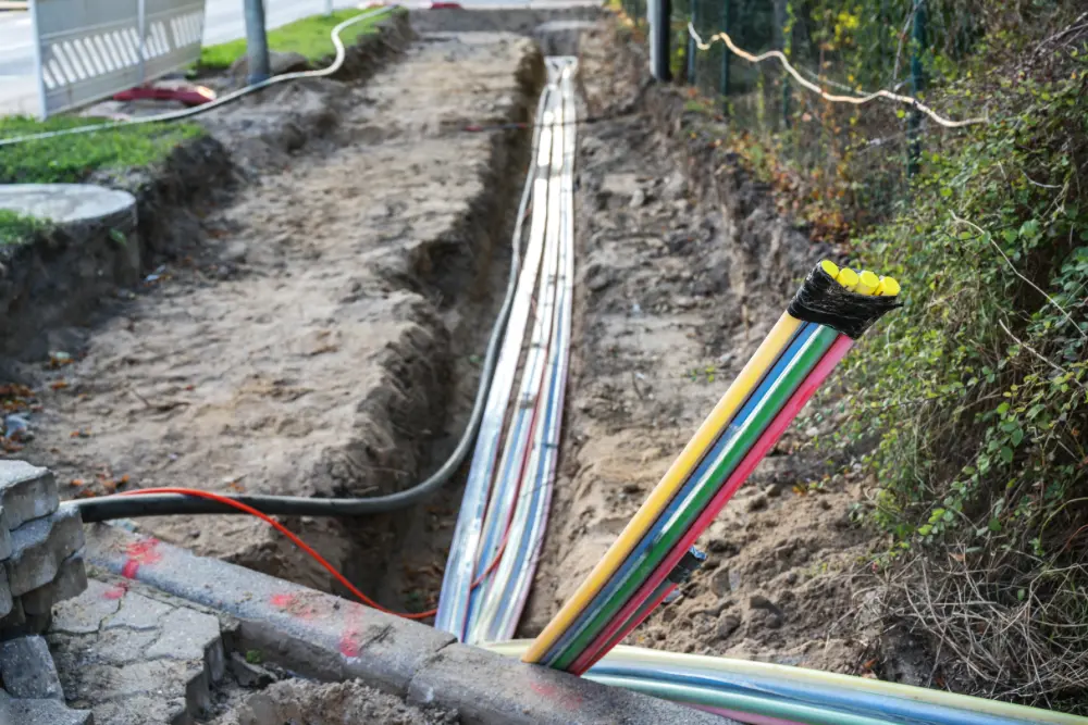
Middle mile infrastructure typically includes:
- Fiber-optic cables
- Microwave or fixed wireless links
- Regional data centers or network hubs
- Aggregation points for multiple local networks
In practical terms, imagine a rural town where a small ISP serves residents and local businesses. The ISP might have its own last mile infrastructure—wires and routers that deliver internet directly to users—but without a robust middle mile connection to a larger urban hub or data center, that service will be slow, unstable, or prohibitively expensive.
In late 2024, the California Department of Technology (CDT) sealed two more joint-build agreements with the Karuk Tribe in the northern part of the state and the Gateway Cities Council of Governments in the southern part of the state. These joint-build partnerships pave the way for 46 miles across county and tribal lands and a 73-mile stretch of network in southeast Los Angeles County, connecting 26 cities, many of them historically underserved communities.
“We are entering into an era of co-management where work together with our state partners to manage these lands which requires an adaptive process,” said Karuk Tribe Chairman Russell Attebery. “The Middle-Mile Broadband Initiative is an integral part of that process. Broadband is not just public safety and education, but also a life-changing instrument and we are partnering with the state to ensure that the next generations of the Karuk people can survive and have a better quality of life.”
“Low-income communities are behind technologically – and business as usual has left communities in several areas of California with a digital divide,” added Vilma Cuellar-Stallings, Board President Gateway Cities Council of Governments and Paramount City Councilwoman. “We are grateful that the California Department of Technology worked with the cities in Southeast Los Angeles County to narrow our digital divide and that of communities like ours, bringing high-speed fiber optic access to underserved Californians.”
California’s Middle-Mile Broadband Initiative is designed to ensure that the state’s residents have a resilient, open-access broadband network with high-speed internet. In addition to the 3,000 miles of middle-mile construction that is ongoing, other program highlights include:
- 10 Tribal joint-build partnerships and engagements
- All 58 counties reached
- 7,233 miles in lease/purchase partnership
- 4,000 miles under construction by Spring 2025
“We are building critical broadband infrastructure across the state to ensure a California where everyone has reliable access to the internet,” said California State Chief Information Officer and CDT Director Liana Bailey-Crimmins. “We are grateful to the Biden-Harris Administration and our state and local partners working with us to close the digital divide.”
How the Internet Is Structured: Backbone, Middle Mile, Last Mile
To understand where middle mile fits, it’s helpful to consider the three-tier structure of internet connectivity:
- Backbone – The internet’s global core, composed of ultra-high-capacity fiber optic networks that span continents and oceans. These are operated by large network providers and connect major cities, countries, and continents.
- Middle Mile – The regional link that connects local ISPs, anchor institutions (like schools and hospitals), and government networks to backbone infrastructure. It includes regional transport networks and routing facilities.
- Last Mile – The final connection to individual end users—homes, schools, libraries, and businesses. This is often where consumer-facing ISPs operate, delivering broadband via cable, DSL, fiber, or wireless.
All three segments must work together to deliver high-speed, reliable internet. Weakness in any one part limits the entire system.
Why the Middle Mile Matters
The middle mile is often a hidden barrier to broadband expansion. While many funding and development programs focus on subsidizing last mile access, local providers still need affordable, high-capacity middle mile connections to deliver competitive service. This becomes especially problematic in remote or rural areas, where middle mile infrastructure is limited or nonexistent.
Key reasons why the middle mile matters:
- Cost Efficiency: If ISPs don’t have access to open and affordable middle mile networks, they may be forced to lease capacity from private carriers at high rates—costs that are passed on to consumers.
- Network Performance: Congested or outdated middle mile networks limit bandwidth and cause latency, reducing the overall quality of service even if the last mile infrastructure is modern.
- Scalability: Robust middle mile networks allow communities to add more users and services—such as public Wi-Fi, smart grid applications, or remote learning—without overloading the system.
- Redundancy and Resilience: Middle mile investments support redundant routes, improving service uptime and disaster recovery in the event of outages.
Challenges to Implementation
While middle mile development is gaining momentum, challenges remain:
- High Capital Costs: Fiber builds, especially over long distances, are expensive and time-consuming.
- Geographic Barriers: Terrain and rights-of-way issues complicate deployment in mountainous or rural areas.
- Permitting and Coordination: Infrastructure projects often require coordination across jurisdictions and utility owners, slowing progress.
For middle-mile broadband infrastructure to truly benefit the communities in which it’s being installed, it first must be installed safely and without damaging existing buried infrastructure.
GPRS safeguards existing and new infrastructure through our subsurface damage prevention, existing conditions documentation, and facility & project management services.
Our utility locating services utilize ground penetrating radar (GPR), electromagnetic (EM) locating, remote-controlled sewer pipe inspection crawlers and push-fed sewer scopes to locate and map buried infrastructure in your project area so you can avoid it when microtrenching or directional drilling. This ensures you avoid costly and dangerous subsurface damage, including cross bores.
SiteMap® (patent pending), GPRS’ infrastructure mapping software application, stores all this accurate, field-verified data in one secure, yet easily accessible platform. You’ll be able to view and share this information with your project team from any computer, tablet, or smartphone.
From skyscrapers to sewer lines, GPRS Intelligently Visualizes The Built World® to keep your projects on time, on budget, and safe.
What can we help you visualize?
FREQUENTLY ASKED QUESTIONS
Can GPRS find PVC piping and other non-conductive utilities?
GPR scanning is exceptionally effective at locating all types of subsurface materials. There are times when PVC pipes do not provide an adequate signal to ground penetrating radar equipment and can’t be properly located by traditional methods. However, GPRS Project Managers are expertly trained at multiple methods of utility locating.
What size pipes can GPRS inspect?
Our elite VPI Project Managers have the capabilities to inspect pipes from 2” in diameter and up.
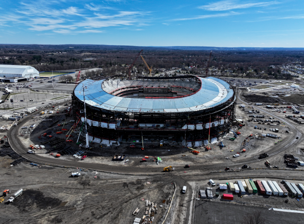
GPRS safety partners Gilbane and Turner Construction recently topped out the Buffalo Bills’ $2.1 billion New Highmark Stadium in Orchard Park, New York.
GPRS safety partners Gilbane and Turner Construction recently topped out the Buffalo Bills’ $2.1 billion New Highmark Stadium in Orchard Park, New York.
The milestone marks the halfway point of the joint venture project that broke ground twenty months ago and is expected to be completed prior to the 2026 NFL season, according to a press release issued by New York Governor Kathy Hochul’s office.
“Today marks a major milestone for the future home of the Buffalo Bills and one of the largest construction projects ever in Western New York,” Hochul said. “This world-class stadium would not be possible without our skilled union workers and partners, and I look forward to cheering along with them at the first Bills game being played here in the 2026 season.”
Hochul and other politicians were joined by NFL Commissioner Roger Goodell, project stakeholders, hundreds of union workers, and more than 1,400 guests at the topping out ceremony, during which the final structural steel beam was placed in the Bills’ future, 60,000-seat home. Kansas City, Missouri-based architecture firm Populous designed the stadium which is right next to the team’s existing facility.
According to the press release, in addition to structural steel work, project teams have removed 742,000 cubic yards of dirt and installed over 46,000 cubic yards of foundation concrete in addition to placing miles of piping. As many as 1,500 workers will be on site at peak construction.
Construction will now turn to the interior of the building as well as on the roof. The Gilbane/Turner joint venture is currently constructing a 360-degree canopy structure at the stadium’s uppermost level, which will extend to a height of 116 feet above grade. At the same time, the team is setting precast components that will shape the building’s exoskeleton, ahead of installing the exterior envelope this spring — which will include precast architectural panels, perforated metal, and glass elements.
Once complete, New Highmark Stadium will also include:
- Heated concourses and seating in several areas
- The world’s largest snow melt system, which will utilize roof sensors to monitor and liquefy snow piles
- Two video boards and an acoustic system
- A mix of concessions, kitchens and retail stores
“We’re incredibly proud to reach this major milestone in the construction of the new Highmark Stadium,” said Gilbane Principal-in-Charge John LaRow. “This achievement is testament to the hard work of our skilled trade partners who have worked over 1.8 million hours to date building this state-of-the-art facility. Thanks to the incredible collaboration with the Buffalo Bills, the Gilbane | Turner team, Populous, Legends and the support of the State of New York and Erie County, this stadium will serve as a proud beacon for the region and showcase the very best in professional sports venues.”
Gilbane/Turner Program Director Joe Byrne said the topping out milestone “marks more than the structural progress of a stadium.”
“It reflects the spirit and strength of the Buffalo community,” Byrne said. “We are deeply grateful to the Buffalo Bills, our dedicated staff and trade partners and the thousands of union tradespeople – so many of whom call this region home – whose skill and commitment are bringing this landmark project to life. It is profoundly meaningful that members of the community are helping to build a venue that will serve as a source of pride and celebration for generations to come.”
“This topping out milestone at New Highmark Stadium stands as a testament to the positive impacts development done under project labor agreements and with prevailing wage measures can have on our local communities and collective state economy,” added New York State Building and Construction Trades Council President, Gary LaBarbera. “The construction of this new home for The Buffalo Bills is generating thousands of family-sustaining careers, adding economic stimulus to our neighborhood, and providing hard-working people in the Western New York region accessible pathways to the middle class. We thank Governor Hochul for her efforts in pushing this project forward and look forward to continuing our role in creating a world-class venue for Buffalo football fans and players alike.”
Whether you’re building a 60,000-seat football stadium or renovating an office building, GPRS supports your construction projects through our comprehensive suite of subsurface damage prevention, existing conditions documentation, and construction & facilities project management services. We offer precision concrete scanning and utility locating, pinpoint-accurate leak detection, NASSCO-certified sewer line inspections, 2-4mm accurate 3D laser scanning, and in-house mapping & modeling tailored to your project’s specific needs.
All this accurate, actionable data is at your fingertips 24/7 thanks to SiteMap® (patent pending), GPRS’ project & facility management application that provides accurate existing conditions documentation to protect your assets and people.
From skyscrapers to sewer lines, GPRS Intelligently Visualizes The Built World® to help keep you on time, on budget, and safe.
What can we help you visualize?
Frequently Asked Questions
Will I need to mark out the utilities that GPRS locates?
GPRS will locate and mark all utilities for you. We have a variety of tools and markers we can use to highlight the locations of utilities, underground storage tanks and whatever else may be hiding.
What is the difference between a design intent and as-built model?
DESIGN INTENT – deliverables will be shown as a "best fit" to the point cloud working within customary standards, such as walls being modeled 90 degrees perpendicular to the floor, pipes and conduit modeled straight, floors and ceilings modeled horizontal, and steel members modeled straight. This will produce cleaner 2D drawings and will allow for easier dimensioning of the scan area. The deliverables will not exactly follow the scan data to maintain design intent standards. Most clients will want this option for their deliverables.
AS-BUILTS – deliverables will be shown as close as possible to actual field capture. If walls are out of plumb, pipes and conduit show sag, floors and ceilings are unlevel, steel members show camber, etc., this will be reflected in the model. This will produce reality-capture deliverables, but 2D drawings may show “crooked” or out of plumb lines, floors will be sloped or contoured, steel members may show camber, twisting or impact damage. Dimensioning will not be as easy due being out of plumbness/levelness, etc. This option should be used when the exact conditions of the scan area is imperative. Clients using the data for fabrication, forensic analysis, bolt hole patterns, camber/sag/deformation analysis, and similar needs would require this option.
GPRS Provides 600 ft. of Concrete Anchor Clearances for a California Apartment Build
GPRS’ industry-leading 99.8% accurate concrete scans helped contractors in California drill with confidence and keep their project moving forward without the risk of delays or injuries.
Shaw & Sons Concrete Contractors were part of the team converting an existing building into an apartment complex in Los Angeles, California. Part of the project included installing walls by anchoring dowels, long, cylindrical steel rods used to bind concrete slabs and secure structures. The contractors knew where they would likely be cutting and coring the concrete, but didn’t know what infrastructure lay beneath it.
A team of GPRS Project Managers was able to arrive on site a full day ahead of schedule to provide our 99.8% accurate concrete imaging services and give Shaw & Sons the peace of mind they needed to pierce the concrete safely.
GPRS empowers our Project Managers to properly assess the scope of work before they begin scanning. For our team to understand the project’s needs, Project Managers and our customers assess the job scope with both pre- and post-job site walks. Doing so also allows our customers to understand the data we’ve provided when the job is complete.
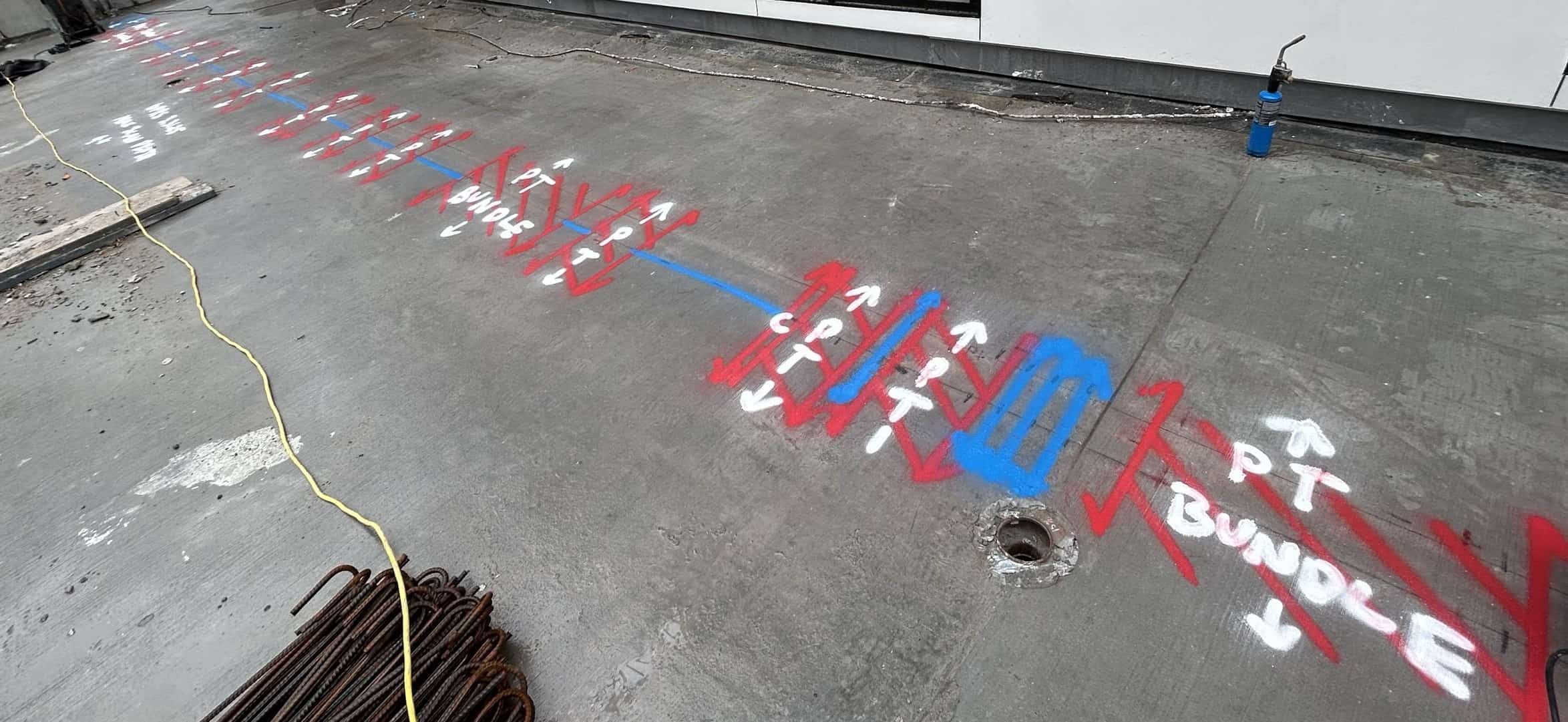
In this case, Project Manager Jason Osuna’s pre-job fact-finding mission included the information that the slabs he would be scanning were post-tensioned.
“Once we know it's post tension, you know to try and identify the pattern of everything,” Osuna explained. “We were quick to see that it was indeed PT, but it did also have everything else, such as conduit and rebar.”

The scanned area totaled approximately 590 feet of concrete. For comparison, that is over 100 feet longer than the length of the Hollywood sign which is 450 feet in length. Osuna was up for the challenge, because post-tensioned concrete slabs generally contain specific, definable characteristics and the SIM process (Subsurface Investigation Methodology) provides a consistent, repeatable procedure to find, image, and mark it all.
“That's probably one of the biggest scans I've done length-wise,” Osuna said. "Usually everything’s simple, but as far as my biggest project, that has been my biggest one.”
With the guiding principles that SIM provides, GPRS Project Managers deliver highly accurate results that lead to lower hit rates. Through experience-based training and multiple technological strategies, they are given proven protocols to follow that consistently provide clients with the information they need.
As the Project Managers collected the data from the scans, it became clear that some of the planned drilling sites were too congested with PT cables for assured clearance, so Osuna and his team discussed alternatives with the concrete contractor.
“Sometimes we have to be the bearer of bad news and tell them this area isn't going to work,” Osuna explained. “That's when we go ahead and propose if they can possibly move the area or move the locations, because of the amount of post tension cables and the amount of damage it can do if struck.”
The cost of replacing a single PT cable is between $20,000 and $30,000. Not only is there a large monetary risk, but each PT cable pulls between 24,000 and 33,000 pounds of pressure, so the physical risks of striking one can’t be underestimated either.
Despite being surprised at the volume of reinforcements within some areas they planned on drilling, the client was appreciative of the accuracy of the data Osuna and his team gathered, and grateful for their ability to get this job done earlier than expected. The initial scanning job took roughly four days, and the team expects to be called back to scan remaining areas that were not accessible at the time.
When speaking with Osuna about this job, he wanted to thank his team, fellow Project Manager Angel Marin and Project Manager Trainees Jesus Ruiz and Daniel Huerta, for their help on this project.
“It was a long and lengthy project, but at the end of the day, with collaboration and teamwork, we were able to get it done.”
Without GPRS’ SIM-certified Project Managers and precise concrete scans, any concrete coring or drilling during this project could put workers’ lives at risk.
What are Post Tension Cables and Why is it Important to Avoid Them When Drilling or Coring Concrete?
Post-tensioning is a technique in which steel cables, also referred to as tendons, are tensioned after the concrete has been cast, which allows for thinner slabs, longer spans, and fewer joints.
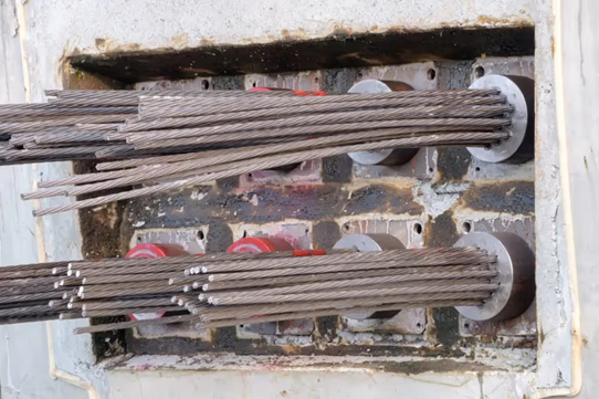
Post tensioned concrete is widely used in commercial, residential, and industrial building projects because of its strength and efficiency. The tendons also play a critical role in the structural integrity of the structure, which is why knowing their exact location is so important.
Just because you’re cutting concrete doesn't mean you can cut corners. Whether it’s a simple repair or full renovation, it’s important to locate post tension cables before drilling can begin. Cutting into a post tension concrete slab without the proper preparation can lead to sudden cable recoil, expensive repairs, severe injuries or death, or compromising the structural integrity of the building.
Hiring concrete scanning professionals like GPRS lowers the chances of accidents or injuries, while keeping each project on time and on budget.
GPRS SIM-certified Project Managers are trained to locate and identify post tension cables and other obstructions with our industry-leading 99.8% accurate concrete scans. By combining Ground Penetrating Radar (GPR) and electromagnetic (EM) locating, Project Managers provide clients with a comprehensive understanding of post tension cables and other infrastructures embedded within their concrete slabs. By doing so, clients can drill or core into concrete with confidence knowing there are no surprises waiting for them.
From a single slab to the size of skyscrapers, GPRS helps you Intelligently Visualize The Built World® by showing you what you need to see before cutting or coring concrete.
What can we help you visualize?
Why Microplastics May Make Pesticides More Dangerous for Agriculture
Microplastics and pesticides are two of the most widespread pollutants in our environment – but new research shows that the real danger may lie in how these two interact.
A February 2025 report by Beyond Pesticides, based on a review of over 90 scientific studies, concludes that microplastics don’t just exist alongside pesticides — they change how pesticides behave, making them more toxic, more persistent, and harder to control.
The researchers say that this interaction has serious consequences for soil health, food production, water quality, and the health of both people and wildlife. Here's what their research tells us — and why it matters.
Microplastics Are Everywhere — Including in Farmland
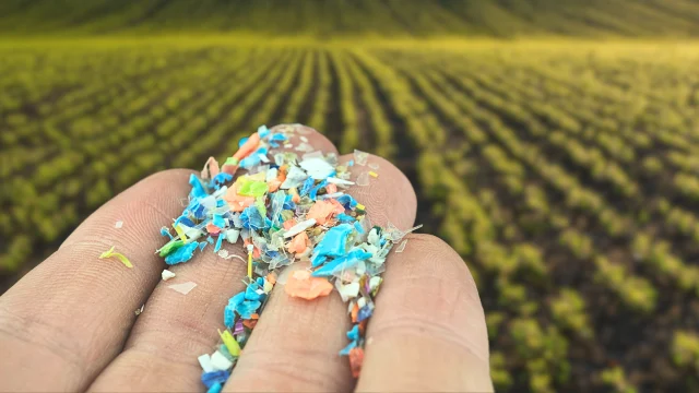
Microplastics are tiny pieces of plastic, often smaller than a grain of rice. They come from larger plastic waste that breaks down over time or they’re manufactured intentionally for use in things like cosmetics, cleaning products, and industrial materials.
Research has shown that the primary contributors to microplastic pollution in water and wastewater include:
- Laundering Synthetic Textiles: Washing clothes made of synthetic materials, such as polyester and nylon, releases microfibers into wastewater systems. These microfibers are classified as microplastics and often pass through treatment facilities.
- Tire Wear: As vehicles move, the friction between tires and roads generates tiny plastic particles. These particles eventually make their way into the environment through stormwater runoff.
- City Dust: Urban areas generate microplastic particles from various sources, including construction materials, vehicle emissions, and discarded plastic waste.
In agriculture, microplastics enter the environment through plastic mulch, fertilizer coatings, treated sewage sludge (biosolids), and pesticide products themselves.
Because of their size and durability, these particles can’t be removed easily and are now considered a global pollutant. They’re found in soil, water, air, and even inside living organisms — including humans. People take them in through the food they eat, the water they drink, and the air they breathe.
Microplastics Change How Pesticides Work
The most important finding in the report is this: microplastics can bind to pesticides and change their behavior.
According to Dr. Kuok Ho Daniel Tang, the University of Arizona researcher who led the study, “Microplastics interact with pesticides through adsorption — basically sticking to their surface — and that changes how long the pesticide lasts, how toxic it is, and how easily it can be taken up by plants, animals, or microbes.”
That means a pesticide’s ability to do its job — killing a pest, fungus, or weed — is reduced or altered. And at the same time, it may linger in the environment longer or end up in places it shouldn’t, like food crops, groundwater, or the bodies of beneficial organisms like earthworms.
Lower Pesticide Effectiveness = More Chemicals Used
One of the more troubling outcomes is that microplastics often reduce how available a pesticide is to the target pest. This is known as “bioavailability.” When microplastics bind to pesticide molecules, those chemicals become harder for pests — or even crops — to absorb. As a result, farmers may apply more pesticide to get the same result.
This creates a dangerous cycle: reduced effectiveness leads to increased use, which increases costs for farmers and further contaminates the environment.
Some examples from the research:
- Microplastics caused a weed killer (atrazine) to break down in the soil before it could work properly
- Aged microplastics absorbed more pesticide than new ones, making pesticides less effective over time
- The combination of microplastics and pesticides reduced seed germination in lettuce and other crops
- Earthworms and other soil organisms showed signs of stress or injury after being exposed to microplastics and pesticides together
Microplastics Make Pesticides Last Longer
In addition to changing how pesticides work, microplastics also affect how long they stay in the environment. This is known as pesticide “persistence.” Normally, pesticides break down after a certain period — called their half-life. But when microplastics are present, that breakdown process slows down.
The report found:
- In water, microplastics extended the breakdown time of herbicides from 231 days to over 800 days
- The presence of microplastics increased the half-life of some fungicides and insecticides by 30–50%
- Some chemicals, like chlorpyrifos, broke down much more slowly when microplastics were present, increasing their chance of causing harm to unintended organisms
- When pesticides hang around longer than expected, they can leach into groundwater, harm aquatic life, and continue to disrupt ecosystems well after their intended use
Soil Health Suffers — Which Affects Food Security
Healthy soil is the foundation of agriculture. But pesticides and microplastics — especially in combination — are damaging that foundation.
The review shows that microplastics can:
- Alter the structure of soil, making it harder to retain water and nutrients
- Reduce microbial activity — the natural bacteria and fungi that help crops grow
- Disrupt the balance of organic matter, making soil less fertile over time
These effects mean farmers may have to rely more heavily on synthetic fertilizers and chemical additives to maintain yields, adding more costs and more pollution.
Microplastics Make Pesticides More Toxic to Wildlife
Even though microplastics reduce how much pesticide is available to the target pests, they often increase toxicity in other ways — especially to beneficial organisms.
When a pesticide sticks to a microplastic particle, and that particle is eaten by an earthworm, aquatic insect, or other organism, it delivers a concentrated dose of pesticide directly into their system. This has been shown to:
- Increase stress and damage in earthworms, including to their reproductive organs
- Reduce growth and antioxidant function in soil organisms
- Increase pesticide buildup in plants like radishes while reducing plant growth.
These ripple effects go beyond individual species. They impact soil fertility, crop production, and entire food webs.
What Can Be Done? Transitioning to Organic Solutions
The findings from this literature review make one thing clear: plastic and pesticide pollution are deeply connected. And solving one means addressing both.
A major solution offered by Beyond Pesticides is transitioning to organic agriculture. Organic systems avoid synthetic pesticides and chemical coatings, and limit plastic use in the field. These practices protect soil health, water quality, and the diversity of organisms needed for sustainable farming.
The National Organic Standards Board (NOSB) — which helps set U.S. standards for certified organic production — is actively reviewing policies on plastics in farming. Groups like Beyond Pesticides are advocating for tighter restrictions on plastic use and increased support for farmers who adopt safer, more sustainable methods.
GPRS supports effective water and wastewater management through our comprehensive suite of leak detection and sewer pipe inspection services.
Our Project Managers utilize acoustic leak detection and leak detection (noise) correlators to help you find leaks and minimize issues such as non-revenue water (NRW) loss, drinking water contamination, and more. And we utilize remote-controlled sewer inspection crawlers, push-fed sewer scopes, dye tracing, and smoke testing to fully inspect your wastewater systems to diagnose and mitigate the consequences of cross bores, inflow/infiltration, collapsed sewer mains, and more.
What can we help you visualize?
Frequently Asked Questions
What size pipes can GPRS inspect?
Our NASSCO-certified VPI Project Managers can inspect pipes from 2” in diameter and up.
What deliverables does GPRS offer when conducting a video pipe inspection?
GPRS is proud to offer WinCan reporting to our Video Pipe Inspection clients. Maintaining sewers starts with understanding sewer condition, and WinCan allows GPRS Project Managers to collect detailed, NASSCO-compliant inspection data. GPRS Project Managers not only inspect the interior condition of sewer pipes, laterals, and manholes – they can also provide a map of their location. The GPRS Mapping & Modeling Department can provide detailed GPS overlays and CAD files. Our detailed WinCan/NASSCO reports contain screenshots of the interior condition of the pipe segments that we inspect, as well as a video file for further evaluation, documentation, and/or reference.
Can GPRS determine the size of a located water line leak?
After analyzing thousands of previous leaks detected, we asked clients to send us pictures of the remediation. This information has helped us compare our final leak signal detected with the results of the actual leak. We determine the size of the leak by how far the leak signal travels between contact points and the pitch of the tone received. However, we do not produce formal leak estimations.
Why don’t I see any water where GPRS has located a leak?
Water finds the path of least resistance. Water can run through cracks in subsurface rock or make its way into storm, sanitary, and conduit piping. If the subsurface contains a high volume of sand, it will naturally flow farther down. There is no water visible on the surface in more than 99% of the leaks we locate.
U.S. Saw Record Investment in New Biogas Systems in 2024
Investment in new biogas projects in the U.S. grew by $3 billion in 2024, according to recently released data from the American Biogas Council.
Between January and December 2024, 125 new biogas projects were launched across the U.S., representing more than $3 billion in new investment. The number of new projects in 2024 rose by 17% compared to 2023, while the total capital invested increased by 40% year over year.
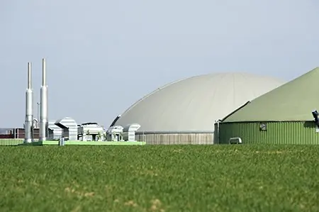
Biogas facilities convert organic waste—including manure, wastewater, food scraps, and captured landfill gas—into renewable natural gas (RNG), electricity, thermal energy, and nutrient-rich fertilizer. Collectively, these segments of the industry generated over 10% more biogas in 2024 than in any previous year.
With the latest additions, the total number of biogas facilities in the U.S. has reached nearly 2,500. These sites now produce close to 1.4 million standard cubic feet per minute (scfm) of biogas, a form of dispatchable renewable energy. That energy output is equivalent to what could be generated by approximately 15,000 football fields covered in solar panels, enough to power 2.4 million homes for a year or to replace the fuel used by 2.6 million gasoline-powered cars.
Biogas also offers significant climate benefits, with a carbon intensity 50% to 700% lower than that of fossil fuels. This is due to the capture of methane—a potent greenhouse gas—that would otherwise be released, and its use as a substitute for fossil energy and synthetic fertilizers.
“The biogas industry keeps hitting new growth records every year because, as an energy source, biogas just makes sense. It provides much-needed clean electricity, cuts pollution and emissions from transportation, and provides heat-producing fuel for industries, all while managing millions of tons of waste from farms and cities alike,” said ABC Executive Director Patrick Serfass. “In a time when demand for domestic energy is increasing significantly, fertilizer markets are constrained by the Ukraine conflict, and America is striving for energy and industrial dominance, the value of 24/7/365 energy and locally produced, natural fertilizer from biogas projects is undeniable.”
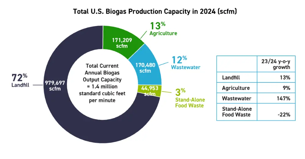
Landfill gas (LFG) projects—which capture methane generated as organic waste decomposes in landfills—account for most of the biogas production in the United States, contributing 72% of total output. This dominant share comes despite the LFG sector having fewer facilities than the agricultural and wastewater segments. In 2024, 24 new LFG projects were brought online, raising the total number of operational LFG sites to 580—a 4.3% increase from the previous year.
These new projects represent approximately $1.4 billion in investment, or 47% of all capital committed to biogas development in 2024. The added capacity pushed the sector’s output up by over 12%, with total LFG production reaching around 980,000 standard cubic feet per minute (scfm). While many of the more recent projects are designed to upgrade biogas into renewable natural gas (RNG), most LFG facilities—roughly 77%—continue to generate electricity from captured methane.
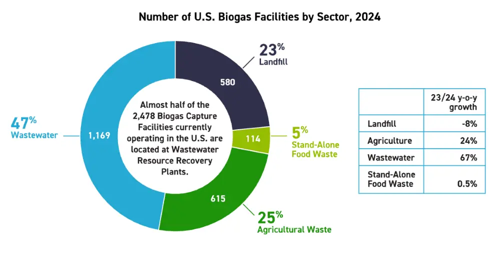
While landfill gas production saw notable gains in 2024, the agricultural sector led in new development, launching 93 farm-based biogas projects—nearly four times the number of new landfill projects. For the first time, the total number of agricultural biogas facilities surpassed landfill-based systems. These new projects represented $1.37 billion in capital investment, primarily in rural areas, and marked a 24% increase over the number of farm projects added in 2023. The sector grew by nearly 18% overall, with total agricultural biogas facilities increasing from 522 to 615. These additions contributed 21,000 standard cubic feet per minute (scfm) of new biogas production. Notably, hog farms saw increased participation, accounting for 29 new projects, or 31% of all new agricultural installations. Farmers continue to explore more efficient methods of managing animal waste.
A major trend in 2024 was the growing emphasis on renewable natural gas (RNG). Of the new agricultural biogas systems, 95% were built with RNG production as their primary goal. RNG projects now outnumber biogas-to-electricity systems in the farming sector by a ratio of roughly three to two.
Although the wastewater sector did not experience the same pace of growth, it continues to represent the largest share of biogas facilities—about 47% of all installations—and boasts the longest operational history. Some of the earliest biogas systems still in use were installed at wastewater treatment plants in the 1920s, using anaerobic digestion to reduce sludge volumes during water treatment.
Standalone food waste biogas systems remain the least common due to their technical complexity. However, three new food waste-only facilities came online in 2024, raising the total to 114. Despite their smaller numbers, roughly 200 agricultural and wastewater biogas systems currently co-digest food waste with manure or biosolids, expanding the sector’s reach. Growth is expected to accelerate in 2025, with 16 dedicated food waste projects already under construction.
Of the 125 new biogas projects developed in 2024, 119—about 95%—were designed to upgrade their biogas into RNG. This trend has been consistent since 2018, largely driven by incentive programs such as California’s Low Carbon Fuel Standard (LCFS) and the federal Renewable Fuel Standard (RFS), which reward producers that cut transportation emissions. Despite RNG’s rise, electricity remains the primary end use for biogas. More than 77% of all biogas facilities, and 60% of total output, are still used to generate renewable electricity—highlighting the ongoing significance of power generation in the sector.
Biogas projects now operate in every U.S. state, as organic waste is a universal byproduct of both human and animal populations. The recent increase in agricultural projects has drawn investment to rural, agriculture-heavy regions. Investment decisions are also shaped by the availability of untapped landfill sites. In 2024, California, Illinois, South Dakota, Pennsylvania, and Virginia saw the most capital invested in biogas projects that came online. The previous year, Michigan, Indiana, Virginia, Ohio, and Texas topped the list.
Each year, Americans send more than 1.4 billion tons of manure, 33 million tons of inedible food waste, and 1 million tons of wastewater biosolids to landfills. Additionally, 470 landfills currently flare methane that could be captured and repurposed. According to the American Biogas Council (ABC), more than 20,000 new biogas systems could still be developed to convert this waste into energy and usable products—creating jobs and reducing emissions in the process.
These future projects have the potential to generate up to 20 gigawatts of continuous electricity, while supporting an estimated 740,000 short-term construction jobs and 25,000 permanent roles in operations. Additional supply chain job creation is also anticipated.
The ABC views biogas expansion as a key economic opportunity. Further industry development could reduce landfill dependence, lower methane emissions, support domestic energy production, provide sustainable fertilizers that enhance crop yield and food quality, and generate well-paying jobs in both rural and urban communities.
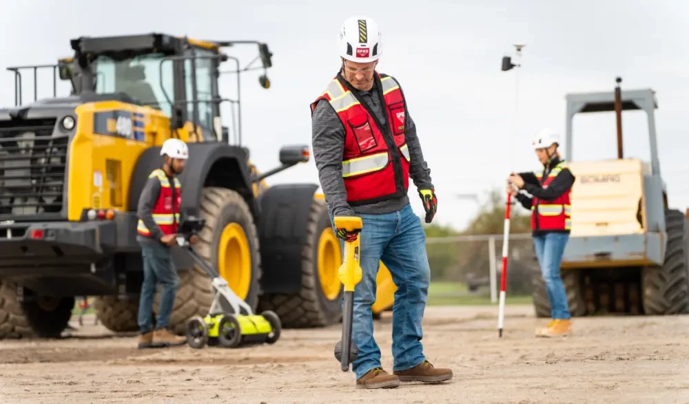
GPRS supports biogas facility projects through our comprehensive suite of subsurface damage prevention, existing conditions documentation, and construction & facilities project management services.
Our 99.8%+ accurate utility locating and concrete scanning services mitigate the risk of subsurface damage when you must break ground. We use 3D laser scanning to capture these markings, as well as all above-ground details for future use. And our in-house Mapping & Modeling Department can use this data to create complete, accurate as-built drawings and 3D Building Information Modeling (BIM).
All this data is at your fingertips 24/7 thanks to SiteMap® (patent pending), GPRS’ project & facility management application that provides accurate existing conditions documentation to protect your assets and people.
GPRS Intelligently Visualizes The Built World® to keep your projects on time, on budget, and safe.
What can we help you visualize?
Frequently Asked Questions
Can you find PVC piping and other non-conductive utilities?
GPR scanning is exceptionally effective at locating all types of subsurface materials. There are times when PVC pipes do not provide an adequate signal to ground penetrating radar equipment and can’t be properly located by traditional methods. However, GPRS Project Managers are expertly trained at multiple methods of utility locating.
Will I need to mark out the utilities GPRS locates?
No, GPRS will locate and mark all utilities for you. We have a variety of tools and markers we can use to highlight the locations of utilities, underground storage tanks and whatever else may be hiding.
What are the Benefits of Underground Utility Mapping?
Having an updated and accurate map of your subsurface infrastructure reduces accidents, budget overruns, change orders, and project downtime caused by dangerous and costly subsurface damage.
How does SiteMap® assist with Utility Mapping?
SiteMap®, powered by GPRS, is the industry-leading infrastructure management program. It is a single source of truth, housing the 99.8%+ accurate utility locating, concrete scanning, video pipe inspection, leak detection, and 3D laser scanning data our Project Managers collect on your job site. And the best part is you get a complimentary SiteMap® Personal Subscription when GPRS performs a utility locate for you.
Does SiteMap® Work with my Existing GIS Platform?
SiteMap® allows for exporting of data to SHP, GeoJSON, GeoPackage, and DXF directly from any user’s account that either owns or has a job shared to their account. All these file formats can be imported and utilized by other GIS packages if manually imported by the user.
Apple to Invest Over $500B in U.S.
Apple recently announced its plans to spend and invest more than $500 billion in the U.S. over the next four years.
The investment represents the technology company’s largest-ever spend commitment, according to a press release they issued announcing the news.
“We are bullish on the future of American innovation, and we’re proud to build on our long-standing U.S. investments with this $500 billion commitment to our country’s future,” said Tim Cook, Apple’s CEO. “From doubling our Advanced Manufacturing Fund, to building advanced technology in Texas, we’re thrilled to expand our support for American manufacturing. And we’ll keep working with people and companies across this country to help write an extraordinary new chapter in the history of American innovation.”
As part of this broader investment initiative in the U.S., Apple and its partners will establish a new state-of-the-art manufacturing facility in Houston to build servers that power Apple Intelligence—the company’s personal artificial intelligence platform designed to help users write, create, and accomplish tasks with ease. In addition, Apple will double the size of its U.S. Advanced Manufacturing Fund, launch a new training academy in Michigan to develop future American manufacturing talent, and expand its U.S. R&D efforts to drive innovation in cutting-edge areas like silicon engineering.

This $500 billion commitment encompasses Apple’s collaborations with thousands of suppliers in all 50 states, its direct workforce, infrastructure and data centers supporting Apple Intelligence, corporate campuses, and Apple TV+ productions active in 20 states. Apple continues to be one of the nation’s largest taxpayers, having contributed over $75 billion in U.S. taxes in the last five years—$19 billion of that in 2024 alone.
Today, Apple helps support over 2.9 million jobs across the United States through its direct employment, partnerships with domestic suppliers and manufacturers, and the growing ecosystem of developers in the iOS app economy.
Apple’s New Houston Manufacturing Facility
As part of its latest wave of U.S. investments, Apple will partner with manufacturers to begin assembling servers in Houston later this year. A new 250,000-square-foot facility dedicated to server production is scheduled to open in 2026, creating thousands of new jobs in the region.
These servers, which were previously built overseas, play a critical role in enabling Apple Intelligence and form the backbone of Private Cloud Compute—a system that fuses powerful AI performance with what Apple says is the most advanced security framework ever implemented at scale for AI in the cloud.
These servers reportedly lower the power demands of its data centers, all of which are already powered by 100 percent renewable energy. As Apple rolls out Apple Intelligence to users across the country, it also plans to continue expanding its data center footprint in North Carolina, Iowa, Oregon, Arizona, and Nevada.
Apple to Double its U.S. Advanced Manufacturing Fund
As part of this expanded investment effort, Apple is doubling its U.S. Advanced Manufacturing Fund—from $5 billion to $10 billion. Originally launched in 2017 to foster innovation and high-skilled manufacturing jobs nationwide, the enhanced fund will continue driving advanced manufacturing and workforce development across the country.
This expansion includes a multibillion-dollar investment in advanced silicon production at TSMC’s Fab 21 facility in Arizona, where Apple is the largest customer. The cutting-edge plant employs more than 2,000 people and began mass-producing Apple chips last month, marking a major milestone in bringing chip manufacturing to the U.S.
Apple says it designs its silicon to deliver top-tier performance, energy efficiency, and powerful features across its devices. Today, Apple suppliers manufacture silicon components in 24 facilities across 12 states—including Arizona, Colorado, Oregon, and Utah. According to Apple’s press release, these investments fuel thousands of high-paying jobs at American companies such as Broadcom, Texas Instruments, Skyworks, and Qorvo.
So far, Apple’s U.S. Advanced Manufacturing Fund has supported initiatives in 13 states—including Kentucky, Pennsylvania, Texas, and Indiana—helping strengthen local economies, equip workers with valuable skills, and advance a broad range of innovative manufacturing techniques and materials used in Apple products.

Growing Investments in R&D
Apple is continuing to scale its research and development efforts across the United States. Over the past five years, the company has nearly doubled its domestic investment in advanced R&D and plans to further increase that spending as part of its long-term growth strategy.
The company recently unveiled the iPhone 16e, the latest addition to its smartphone lineup. The device features the A18 chip and the newly introduced Apple C1, a cellular modem designed in-house. Apple says the C1 offers improved power efficiency and marks a shift toward designing more of its own modem systems. The modem is the product of multiple years of development and signals the company’s intent to further integrate its silicon architecture across future devices.
Looking ahead, Apple has announced plans to hire approximately 20,000 new employees over the next four years, with most of those roles centered on research and development, silicon engineering, software, artificial intelligence, and machine learning. As part of this effort, the company will continue expanding its R&D footprint across various U.S. hubs, with teams focused on areas such as custom chip design, hardware, and emerging software technologies.
New Manufacturing Academy in Detroit
Apple plans to launch a new Apple Manufacturing Academy in Detroit aimed at helping businesses adopt advanced manufacturing practices. The initiative will bring together Apple engineers and academic experts, including faculty from Michigan State University, to advise small and mid-sized companies on integrating AI and smart manufacturing technologies. The academy will offer free courses—both in-person and online—covering topics such as project management and manufacturing process optimization, with the goal of improving efficiency, productivity, and quality across supply chains.
The company’s broader investment in workforce development includes ongoing support for educational programs targeting U.S. students and workers. That includes grants for national organizations such as 4-H, Boys & Girls Clubs of America, and FIRST, which collaborate with Apple to provide free skill-building opportunities in local communities—particularly in areas like coding and STEM education. Among its other initiatives, Apple’s New Silicon Initiative is designed to prepare students for careers in chip design and hardware engineering. Originally launched at Georgia Tech, the program has since expanded to eight institutions nationwide and will add a new partnership this year with UCLA’s Center for Education of Microchip Designers (CEMiD).
GPRS Intelligently Visualizes The Built World® for customers in the construction, remodel & design-build industries.
What can we help you visualize?
Frequently Asked Questions
Can GPRS handle projects at a national scale?
Absolutely. GPRS has a coast-to-coast team of highly trained, SIM-certified Project Managers, covering all 50 states—including Alaska, Hawaii—and even Puerto Rico. Our teams are frequently engaged in large-scale projects across sectors like energy, retail, environmental services, healthcare, education, infrastructure, and a broad range of industries tied to architecture, engineering, and construction.
You can explore more about GPRS’ national reach here.
How does GPRS manage data delivery for large regional or national projects?
No matter the scale—from a single utility locate to thousands of miles of infrastructure—GPRS ensures every client receives consistent, high-quality service and deliverables. That’s the foundation of SiteMap® (patent pending), our proprietary interactive software platform. Every client is granted free access to SiteMap® Personal, and we also offer tailored SiteMap® solutions for anything from an individual job site to a comprehensive, nationwide facilities portfolio.
How is Utility Locating Done?
The process of utility locating involves identifying and mapping underground utilities such as gas lines, water pipes, electrical cables, telecommunication lines, and sewer lines before excavation or construction. Mapping utility locations ensures safety on the construction site, prevents service disruptions, and avoids costly damage to utilities.
The utility locating process typically follows these steps:
1. Request Existing Utility Records
- Request maps, as-built drawings, and utility records from municipalities, utility companies, local government, public records, engineering firms, or facility managers.
- Review historical data to identify known utility locations.
2. Perform a Site Survey
- If you are planning on digging (on private or public property), you are required by law to contact 811 before you break ground to request a utility locate.
- 811 will contact the utility owner who usually partner with a subcontractor to locate and mark 811-registered public utilities.
- Public utility locating via 811 centers is a free service in the U.S., but 811 centers can only contact registered utility owners to mark their utility lines prior to excavation. Their mission does not extend to notifying owners of unregistered or privately-owned utilities.
- You should also employ a private utility locating service such as GPRS to ensure that there are no private utility lines where you’re intending to dig.
- A trained utility locating technician performs locates for all non-public buried assets. With a nationwide team of elite Project Managers strategically stationed across the country, GPRS ensures you always have a qualified utility locating professional near you.
3. Select Utility Locating Methods
Technicians use specialized equipment to detect and mark underground utilities. The utility locating process utilizes the following equipment:
- Ground Penetrating Radar (GPR): GPR is a non-destructive technology which sends radar pulses into the ground and creates images of subsurface features. It can identify all types of underground utilities and can scan for voids, rebar, conduit, post tension cables, and other structural elements hidden within concrete.
- Electromagnetic Locators: An EM locator is a device used to locate and trace buried metallic utility lines, such as pipes and cables, by using electromagnetic signals. An EM locator can trace the following buried metallic utility lines – electrical cables, telecommunication & fiber optic cables (with tracer wire), metallic gas pipelines, metallic water supply lines, sewer lines & storm drains, and metal pipes used in irrigation systems.
- Acoustic Locators: Acoustic locating detects underground water leaks and traces buried pressurized pipes by analyzing sound waves and vibrations. Specialized sensors and ground microphones amplify these sounds, helping technicians pinpoint leaks and trace non-metallic pipes, such as PVC or HDPE, which do not conduct electromagnetic signals.
- Magnetic Locators: Magnetic locators find buried iron or steel objects such as cast iron or steel water pipes, valve boxes, manhole covers, and other buried infrastructure.
4. Mark Out Utilities
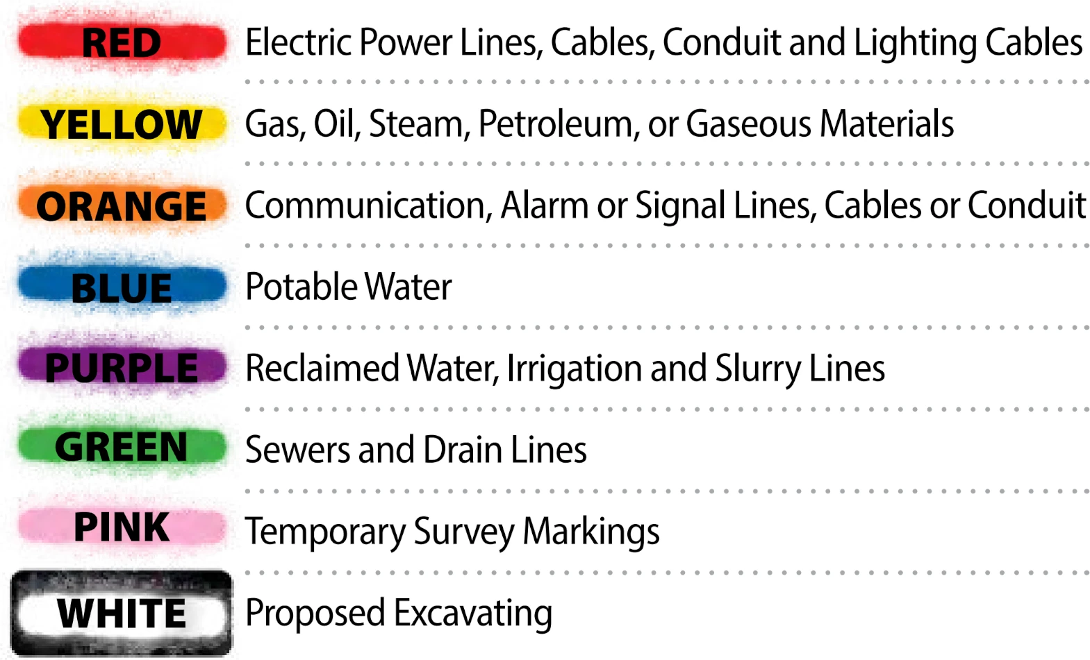
- Utilities are marked on the ground using standardized color codes and symbols to indicate the type and location of buried infrastructure.
- After a utility locating service identifies underground pipes, cables, or conduits, they use spray paint, flags, or stakes to mark their positions.
- Markings often include symbols, letters, or numbers to indicate utility depth, pipe size, or ownership. These ground markings help contractors avoid damage to buried utilities, ensuring safe excavation and construction activities.
- The American Public Works Association (APWA) has established a universal color code to differentiate various utilities:
- Red – Electric power lines, cables, and lighting cables
- Orange – Communication, alarm, signal lines, and fiber optic cables
- Yellow – Gas, oil, steam, petroleum, and other flammable materials
- Green – Sewer and drain lines
- Blue – Potable (drinking) water
- Purple – Reclaimed water, irrigation, and slurry lines
- Pink – Temporary survey markings
- White – Proposed excavation area
5. Verification and Depth Estimation
- Some projects require additional verification through vacuum excavation or potholing, where small holes are dug to confirm depth and location.
- Utility depths are estimated based on signal strength and GPR reflections.
6. Map Utilities in CAD and BIM
- The utility marking field data includes precise spatial coordinates, depths, types of materials, and other attributes. Once collected, this data is typically processed in GIS (Geographic Information Systems) software to organize and visualize the information.
- There are several GIS companies that help clients map their infrastructure; they all share one key challenge: the system is only as accurate as the data entered into it.
- The effectiveness of any GIS system hinges on the quality of the data it uses. If the input data is inaccurate, incomplete, or outdated, the resulting maps and analyses will also be flawed.
- SiteMap® powered by GPRS, is built on accurate, real-world data collected directly from the jobsite by GPRS’ highly trained Project Managers, all of whom are NASSCO and SIM-certified.
- Geospatial data can be exported into precise 2D utility maps in AutoCAD, Civil 3D, or MicroStation formats. Color coding is applied and mapped following the APWA utility marking standards mentioned above for clear visualization.
- AutoCAD: Used for creating accurate 2D utility layouts, AutoCAD is widely accepted in architecture, engineering, and construction. The utility lines, symbols, and annotations can be placed on standardized layers for easy reference and integration into larger site plans.
- Civil 3D: This is a more advanced version of AutoCAD tailored for civil infrastructure projects. Civil 3D allows the geospatial data to be integrated with topography, corridors, and other site design elements, making it ideal for clash detection, grading, and pipe network design.
- MicroStation: Used commonly in DOT and large infrastructure projects, MicroStation supports similar functionality and precision as AutoCAD, enabling teams to visualize utility data in highly regulated formats.
- Each utility is georeferenced to real-world coordinates and organized into standard layering conventions (e.g., separate layers for water, gas, electric, sewer, and telecom).
- Many GPS and GNSS receivers utilize RTK GPS coordinates to achieve a greater degree of positioning accuracy.
- Standard GPS typically offers 1–5 meter accuracy, which is fine for general use but not reliable for precision work like utility locating.
- RTK GPS, on the other hand, uses real-time corrections to achieve centimeter-level accuracy—ideal for surveying, utility locating, and mapping underground infrastructure.
- Because RTK's geolocation is more accurate than a standard satellite image, the actual location of your utilities may not line up with where you expect to see them on the map; not because the utilities are mismarked, but because the utility data has been more accurately captured than the satellite image.
- A 3D BIM model can be generated in software like Revit or Civil 3D, including elevation and depth attributes, for detailed visualization and clash detection.
- As-built utility data can be aligned with site plans, survey data, and as-built drawings.
- By converting GIS geospatial data into CAD and BIM formats, clients get precise, scalable, and easily editable documentation, ensuring safer excavations and more efficient design coordination.
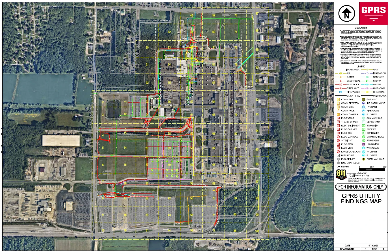
GPRS’ SiteMap® Software Platform
SiteMap® (patent pending), powered by GPRS, is a cloud-based infrastructure mapping application that features GIS functionality, and is able to support data portability for your existing GIS platform of choice
What sets GPRS’ SiteMap® apart from other GIS platforms is its foundation: it's built on accurate, real-world data collected directly from the jobsite by GPRS’ highly trained Project Managers, all of whom are NASSCO and SIM-certified.
Unlike traditional GIS systems that rely on potentially outdated or inconsistent third-party data, SiteMap® is powered by precise field data gathered through advanced utility locating, CCTV sewer inspections, and 3D laser scanning.
This verified data is then processed, layered, and modeled by GPRS’ in-house Mapping & Modeling Department to create clear, customized visuals that align with your project requirements. The result is a secure, cloud-based GIS platform that gives you confidence in your infrastructure data—enabling faster decision-making, safer excavation, and better long-term asset management.
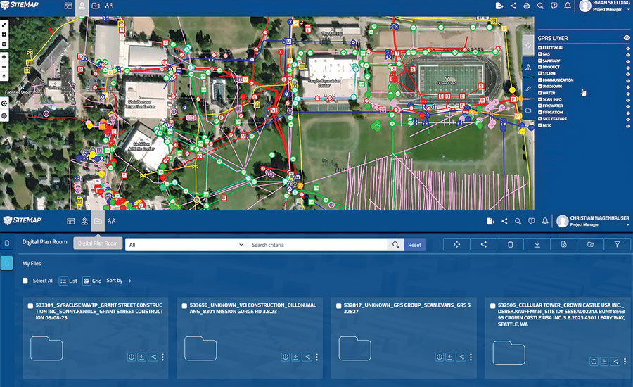
Why Utility Locating Matters
- Prevents costly damages to underground infrastructure.
- Enhances worker safety by avoiding hazardous gas or electrical line strikes.
- Ensures regulatory compliance and prevents legal liabilities.
- Reduces project delays by avoiding unexpected underground obstructions.
By following a thorough utility locating process, construction teams can proceed safely and efficiently without costly or dangerous interruptions.
Why Choose GPRS?
GPRS excels in utility locating because our Project Managers utilize advanced GPR and EM locating technologies, coupled with industry-leading training and methodologies, to achieve 99.8% accuracy in identifying and mapping underground infrastructure.
Our 99.8% accuracy rating is made possible by our elite team of Project Managers who use advanced tools to ensure compliance with Subsurface Investigation Methodology (SIM) standards. SIM focuses on training, equipment expertise, and best methodology practices to safeguard underground assets, limit structural damage, and increase contractor accountability.
GPRS clients are guaranteed reliable utility locating services and the assistance of a Project Manager who provides real-time accurate data in SiteMap®. GPRS clients get a powerful, visual tool that bridges field conditions and office-based design—streamlining workflows from discovery to delivery.
With GPRS, you'll Intelligently Visualize The Built World™ by mapping your subsurface infrastructure to identify potential site issues and risks.
What can we help you visualize?
Frequently Asked Questions
How much does utility locating cost?
The cost of a private utility locate varies depending on the size and specifics of the site being scanned, as well as other factors. Utility locates are not cheap, but as mentioned above they are a vital service and significantly less expensive than the cost – both financial and otherwise – of striking a utility line.
What types of utilities can be located?
Electric, steam, telecommunications, water pipes, gas & oil pipes, sewer pipes & storm sewer lines, and many other primary and secondary utility services can be located.
Does GPRS offer same day private utility locating?
Yes, our professional Project Managers can respond rapidly to emergency same-day private utility locating service calls on your job site.
GPRS Combines Concrete Imaging & 3D Laser Scanning to Aid Resort Casino Renovations
GPRS concrete imaging and 3D laser scanning services provided accurate existing conditions documentation prior to extensive renovations at one of the largest resort casinos in the United States.
Pechanga Resort Casino in Temecula Valley, California was preparing to renovate parts of its hotel, event spaces, and ballrooms.
The contractor working with Pechanga on its renovations would be cutting and coring into elevated concrete slab. They needed to obtain accurate data about the layout of post tension cable, rebar, stud rails, and conduits, so they could avoid all these reinforcements and prevent costly – and potentially dangerous – subsurface damage.
The catch was that the event spaces needed to remain operational during any investigations of the slab.
“They would be needing to use these event spaces and could not have markings down on the ground,” explained GPRS Area Manager David Henneman. “This gave us a limited window to collect/perform the work, and without having the marks remain on the ground there would be very little value to the client.”
Fortunately, GPRS’ comprehensive suite of subsurface damage prevention, existing conditions documentation, and construction & facilities project management services enable us to find creative solutions to our client’s unique problems.
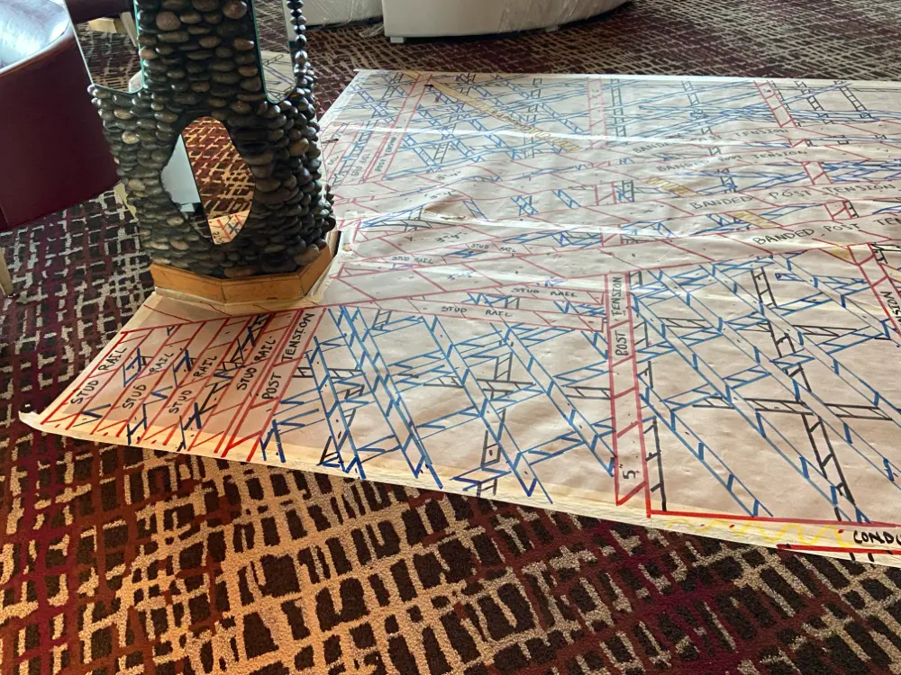
Project Managers Armando Martinez, Jesse Radilla, Steven Gomez, Mazi Richburg, Mario Poblete, and Mike Abel first conducted our standard concrete scanning services using ground penetrating radar (GPR) scanners. This non-destructive imaging technology emits radio waves into a concrete slab, then detects the interactions between those signals and any embedded objects such as rebar, post tension cable, or conduit.
The interactions between the signals and the buried objects are presented in a GPR readout as a series of hyperbolas that vary in size and shape depending on what was located. GPRS’ Project Managers interpret this data to tell you what was found and provide the estimated depth that those items are buried.
Because Pechanga did not want any permanent markings left in their event spaces, the Project Managers marked out their findings on heavy-duty, temporary floor protection which they had laid over the floor prior to scanning.
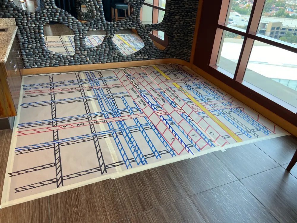
The Project Managers then documented their findings with 3D laser scanners. They also scanned the interior spaces that would be renovated, to provide additional data that would prove invaluable during planning and design.
GPRS 3D Laser Scanning Services quickly and accurately document buildings and infrastructure with Leica laser scanners to deliver LiDAR point clouds, 2D CAD drawings, and 3D BIM models that expedite project planning and execution.
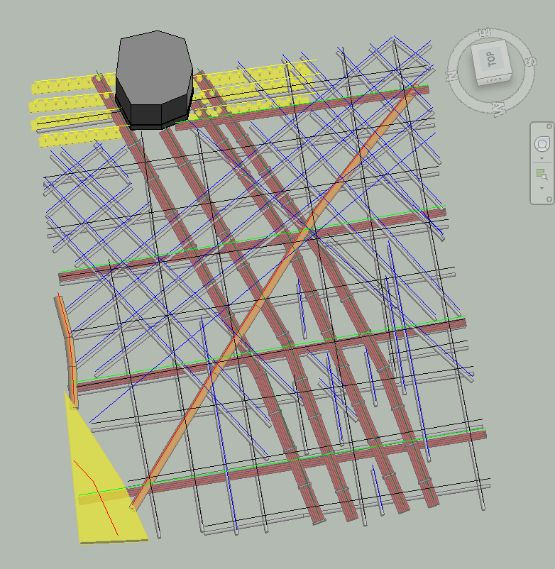
Through the combination of concrete imaging and 3D laser scanning, Pechanga Resort Casino ultimately received a 3D model of the spaces they were planning to renovate, along with 2D CAD drawings of the concrete scanning markings, and a 3D at-depth model of the concrete slab.
“We took this as an opportunity to introduce the use of laser scanning and a 3D model to preserve the findings in an accurate digital twin,” Henneman said. “The scope was originally just scanning areas for items within the elevated concrete deck but ultimately evolved into a laser scan with a full 3D model with rebar, conduits, and post tension modeled at depth.”
Henneman said that the team discovered an extraordinary number of conduits embedded within the slab. Had the contractor not had an accurate map of these conduits, they and their team would have been in danger of damaging one of these lines and electrocuting themselves.
“We knew there were conduits in the slab, but the amount we found was surprising,” Henneman said.
The data collected by GPRS allowed Pechanga Resort Casino to safely and efficiently plan and execute their renovations.
From skyscrapers to sewer lines, GPRS Intelligently Visualizes The Built World® to keep your projects on time, on budget, and safe.
What can we help you visualize?
Frequently Asked Questions
Is 3D laser scanning right for my project?
Almost any project that requires as-built information can benefit from a laser scanning survey. Talk with our experts and start your 3D laser scanning survey project today.
Can ground penetrating radar determine the difference between rebar and electrical conduit?
Ground penetrating radar (GPR) can accurately differentiate between rebar and electrical conduit in most cases. We have an extremely high success rate in identifying electrical lines in supported slabs or slabs-on-grade before saw cutting or core drilling.
Additionally, GPRS can use electromagnetic (EM) locators to determine the location of conduits in the concrete. If we can transmit a signal onto the metal conduit, we can locate it with pinpoint accuracy. We can also find the conduit passively if a live electrical current runs through it.
The combined use of GPR and EM locating allows us to provide one of the most comprehensive and accurate conduits locating services available.
What is a digital twin?
A digital twin is highly complex virtual model that is the exact counterpart (or twin) of a physical object. GPRS uses 3D laser scanners to collect real-time data for a building or facility and create a digital duplicate. Data can be easily visualized, measured and analyzed. Digital twins can be used to improve efficiencies, optimize workflows and detect problems before they occur.
What’s the difference between design intent and as-built documentation?
DESIGN INTENT – deliverables will be shown as a "best fit" to the point cloud working within customary standards, such as walls being modeled 90 degrees perpendicular to the floor, pipes and conduit modeled straight, floors and ceilings modeled horizontal, and steel members modeled straight. This will produce cleaner 2D drawings and will allow for easier dimensioning of the scan area. The deliverables will not exactly follow the scan data to maintain design intent standards. Most clients will want this option for their deliverables.
AS-BUILTS – deliverables will be shown as close as possible to actual field capture. If walls are out of plumb, pipes and conduit show sag, floors and ceilings are unlevel, steel members show camber, etc., this will be reflected in the model. This will produce reality-capture deliverables, but 2D drawings may show “crooked” or out of plumb lines, floors will be sloped or contoured, steel members may show camber, twisting or impact damage. Dimensioning will not be as easy due being out of plumbness/levelness, etc. This option should be used when the exact conditions of the scan area is imperative. Clients using the data for fabrication, forensic analysis, bolt hole patterns, camber/sag/deformation analysis, and similar needs would require this option.
Exploring Digital Solutions for LCRI and LCRR Compliance
As the U.S. Environmental Protection Agency (EPA) tightens its regulations around lead and copper in drinking water, water systems across the country are under increasing pressure to comply with the Lead and Copper Rule Improvements (LCRI) and the Lead and Copper Rule Revisions (LCRR).
With deadlines looming and complexity mounting—particularly around inventory development, customer communication, and service line replacement—utilities are turning to digital tools to help bridge the compliance gap.
Digital transformation isn’t just a buzzword; it’s becoming a lifeline for water systems trying to meet federal requirements in a cost-effective, scalable, and timely manner. From asset management software to cloud-based GIS platforms and AI-powered data analytics, technology is playing an essential role in preparing for both LCRI and LCRR compliance.

Understanding LCRR and LCRI
The LCRR, published in January 2021, mandates that all community water systems develop a comprehensive inventory of both utility- and customer-owned lead service lines (LSLs) by October 16, 2024. This requirement includes identifying the materials used in service lines and creating a plan to replace those containing lead.
The LCRI builds on the LCRR by clarifying which LCRR provisions will be maintained and detailing new LCRI requirements and compliance deadlines. Together, these rules represent a significant shift in how lead is managed in drinking water systems, necessitating stronger visibility, communication, and accountability across utility operations.
The Compliance Challenge
Meeting these requirements poses numerous challenges:
- Identifying unknown service lines: Many utilities lack complete records of materials used in service lines, particularly on the customer-owned portion. Many more lack accurate data of these lines’ locations.
- Data management: Accurate and accessible data is essential for regulatory reporting and public transparency.
- Customer coordination: Because the rules apply to both sides of the service line, utilities must engage with customers to inspect and, if necessary, replace customer-owned pipes.
- Resource constraints: Smaller utilities may struggle with the staffing, technical expertise, and funding needed to implement compliance plans.
These challenges underscore the need for digital innovation that can streamline data collection, enhance public engagement, and drive informed decision-making.
Digital Solutions: The Path Forward
1. Asset Management & GIS Platforms
Geographic Information Systems (GIS) play a central role in LCRR compliance, enabling utilities to create interactive, map-based service line inventories. These platforms allow for the integration of historic records, field inspection data, and predictive modeling to categorize service line materials with greater confidence.
2. Predictive Analytics and Machine Learning
Where historical data is missing or inconclusive, machine learning algorithms can help fill in the gaps. By analyzing patterns in existing data—such as construction era, property records, or neighborhood characteristics—AI models can predict the likelihood that a service line contains lead.
This predictive approach allows utilities to target investigations and reduce the need for costly, labor-intensive field verification. The EPA has acknowledged predictive modeling as an acceptable methodology for categorizing unknown lines, provided that the approach is transparent and documented.
3. Cloud-Based Platforms for Data Collection and Reporting
Cloud-based tools enable seamless data entry from the field, centralize customer service interactions, and automatically generate compliance documentation. They also provide templates for customer notifications, educational materials, and sample result letters, ensuring that communication aligns with regulatory expectations.
4. Customer Engagement Tools
Given the importance of customer-owned service lines in both LCRR and LCRI, public engagement is a critical success factor. Digital tools help streamline this process through customer portals, online self-reporting forms, and automated outreach campaigns.
For example, utilities can deploy digital surveys that ask homeowners to identify the material of their service lines using photos or inspection guides. The data collected through these platforms feeds directly into the utility’s inventory and reduces the need for on-site visits.
Some platforms also allow customers to schedule inspections or replacements directly online, improving responsiveness and satisfaction while reducing administrative burden.
5. Mobile Field Data Collection
Mobile applications used by field crews can dramatically improve the speed and accuracy of service line verification. With GPS-tagged photos, drop-down menus for materials identification, and cloud syncing, field data can be uploaded in real time and integrated with GIS systems.
This eliminates paper-based recordkeeping, minimizes data entry errors, and enables immediate analysis. Teams can also access customer records and work orders from the field, improving operational efficiency.
Funding and Scalability
Federal funding from the Bipartisan Infrastructure Law (BIL) is helping make digital transformation more attainable. Many states are channeling funds from the Drinking Water State Revolving Fund (DWSRF) into technical assistance and infrastructure upgrades. These funds can be used to purchase software, train personnel, and digitize historical records—an essential first step for compliance.
However, scalability remains a concern. Smaller and rural systems may need more targeted support, especially when it comes to deploying predictive analytics or cloud-based inventory platforms. Regional partnerships and shared service models can help spread costs and expertise across neighboring utilities.
Preparing for the Future
With the LCRR compliance deadline less than a year away and LCRI rulemaking on the horizon, utilities must act now. Digital tools offer a pathway not just to compliance, but to long-term resilience and operational excellence.
GPRS offers 99.8%+ accurate utility line location and mapping, and NASSCO-certified video pipe inspection (VPI) services to accurately map all your storm and sanitary sewer lines, laterals, and to find cross bores caused by trenchless technology (directional drilling). We ensure you have a comprehensive map of your entire drinking and wastewater systems to make finding and replacing LSLs much faster and easier.
Further, every GPRS customer receives access to SiteMap® (patent pending), our interactive infrastructure visualization software that provides you with layered, interactive utility maps and NASSCO WinCan reports in a secure, cloud-based platform, so you can control the quality of your water infrastructure information and who has access to it. SiteMap® allows you to put the right information into the right hands, at exactly the right time.
What can we help you visualize?
Frequently Asked Questions
How can I tell if my building has lead pipes that need to be replaced?
If you have access to the original record drawings that include MEP (mechanical electrical & plumbing) specifications, you may be able to determine the material of the original pipes. However, most record drawings are inaccurate and do not include renovations and updates. The conscientious process to assess and remove LSLs is to hire an expert utility locating company near you to locate your pipes so you can limit potholing to determine their material.
Learn more about GPRS 99.8%+ accurate utility locating and mapping, here.
How 3D Laser Scanning Ensures Fair Competition in Yacht Racing
Precision is essential when scanning buildings and facilities in preparation for restoration, renovation, or expansion projects. This is also true in the world of racing yachts which is why the Offshore Racing Congress (ORC) has turned to 3D laser scanners.
The ORC has been overseeing the measurement of yachts for over 50 years to ensure each vessel can race fairly against their competitors. Each yacht can differ in size and design, so handicaps are necessary to keep the races fair and adjust race times accordingly. The criteria for these handicaps include some the following:
- The vessel’s size and weight
- The configuration of the hull, which is the body or frame of the ship that is mostly underwater when racing
- The shape of the ship’s appendages, which are parts that extend beyond the main hull such as propellers and rudders
- The dimensions of the sails
There is a long list of items that require precise evaluation. Before the implementation of 3D laser scanners, the ORC relied on manual tools and techniques, including hand measuring, that would take a long time to get the yacht’s true dimensions. Due to the possibility of human error, they would often struggle to capture these measurements with precision, and even the slightest inaccuracies can affect the outcome of a race.
The application of 3D laser scanning allows them to capture the information and measurements needed in a fraction of the time the traditional approaches would take.

In the summer of 2024, ORC ran a trial run for 3D laser at a shipyard in Finland using the Leica RTC360 terrestrial laser scanner. The results showed that the time needed to precisely document the ship’s shape was around three hours, when it would typically take six.
Similar to GPRS’ 2-4mm accurate scans in the architecture, construction, and engineering industries, ORC stated each scan achieved a resolution of 3mm from a range of 10m. The collected point cloud data, which is a virtual 3D dataset of the scanned area, helped create a detailed 3D model of the yacht. Every essential measurement needed to properly assess the vessel was captured in this model.
Are 3D Scans Used in Other Sports?
3D laser scanning has been making its way into the sports industry to help make sure that athletes, coaches, and trainers keep pace with the constantly evolving world of athletics. The incredible precision of 3D scans allows for a greater level of customization to meet the needs of athletes.
One way 3D laser surveys are revolutionizing sports is in training assessments. By collecting scans of athletes’ bodies, the results provide exceptional insights into their physique and movements. With a precise outlook of the athlete’s biomechanics, coaches and trainers can develop customized training programs to improve their performance and reduce the risk of injury.
Another way 3D laser scanning is used in sports is with equipment design. From custom-fitted shoes to helmets, 3D scans can be used to create sports equipment that enhances both comfort and performance for athletes.
3D laser scanning is not only transforming the world of yacht racing and sports as a whole, but, with professional 3D reality capture companies like GPRS, it is changing the way architectural and construction projects are planned and managed.
How Does GPRS Utilize 3D Laser Scanning?
GPRS 3D laser scanning services help clients Intelligently Visualize The Built World® by providing them with highly accurate as-builts and existing conditions documentation. GPRS’ 3D laser scanning services include:
Just like with yacht measurements, hand-measured as-built drawings can be a waste of time and money. Manual measurements are typically inaccurate, which can lead to costly mistakes and project delays. GPRS’ 2-4mm accurate scans and 2-6mm accurate deliverables create detailed and complete as-builts to show clients what they need to see.
Architectural 3D Laser Scanning
The precision and accuracy of 3D laser scanning captures the level of detail necessary for architectural projects. The full documentation of a site or building’s existing conditions helps make sure no inaccuracies or unseen issues arise during the project.
GPRS’ experience in architectural scanning, modeling, and data management helps eliminate site revisits and provides comprehensive as-built documentation that is unmatched by other technologies.
3D Laser Scanning in Construction
For general contractors, securing accurate measurements by hand is often a challenge and can even pose the risk of injury. With the help of 3D laser scanning, general contractors can better design and visualize their plans with highly accurate as-built drawings and measurements captured in a fraction of the time.
Intelligently Visualize The Built World® with GPRS, where we strive to keep your projects afloat even through the roughest waters. What can we help you visualize?
FREQUENTLY ASKED QUESTIONS
What Deliverables Can GPRS Provide?
Our in-house Mapping & Modeling Department can provide 3D modeling in many formats, including:
- Point Cloud Data (Raw Data)
- 2D CAD Drawings
- 3D Non-Intelligent Models
- 3D BIM Models
- JetStream Viewer
Customizable deliverables upon request include:
- Aerial Photogrammetry
- Comparative Analysis
- Deformation Analysis
- Digital Drawings of GPR Markings
- Floor Flatness Analysis/Contour Mapping
- New Construction Accuracy Analysis/Comparative Analysis
- Point Cloud Modeling Training Webinars
- Reconciliation of Clients 2D Design Drawings
- Reconciliation of Clients 3D Design Model
- Structural Steel Shape Probability Analysis
- Template Modeling
- Volume Calculations
- Wall Plumb Analysis
What is LiDAR?
LiDAR is a remote sensing method used to generate precise, three-dimensional information about the shape of an object and its surface characteristics. Much like radar systems that employ radio waves to measure objects, LiDAR uses lasers to calculate the distance of objects with light pulses from 3D laser scanners, gathering 3D information about an object.
What is BIM?
BIM stands for Building Information Modeling and is more than just a 3D model. 3D BIM scanning gives engineers the ability to manage the building data throughout its whole life cycle. It provides accurate spatial relationships and manufacturer details, as well as geographic information and other pertinent aspects of the building.
Construction Begins on $1 Billion Transit-Oriented Community in Miami
Miami-Dade County, together with South Florida residential and commercial development firm, Terra, recently broke ground on a $1 billion mixed-use Transit-Oriented Community (TOC) in west Miami Dade.
According to a press release issued by the county, Upland Park is being built adjacent to the Dolphin Park and Ride Metrobus Station.
“Through public-private partnerships, we are accelerating smart solutions by adding new transit-oriented communities along major transit corridors,” said Miami-Dade Mayor Daniella Levine Cava. “These developments provide public transportation connections to employment centers, schools, arts and culture, and healthcare, making it easier for residents to access essential services and opportunities. Upland Park is a prime example of how we are continuing to build a better community for all and a future-ready Miami-Dade County. Located alongside the 836 Expressway, which features a dedicated bus lane, this development will provide residents with seamless and efficient transit options, further integrating smart mobility solutions into our growing region.”

Also known as Transit-Oriented Development (TOD), Transit-Oriented Communities typically include a mixed-use of housing, office, retail space, and/or amenities integrated into a walkable neighborhood and are located within half a mile of public transportation.
TOCs improve access to housing and employment for people of all ages and income levels. These thoughtfully designed areas strengthen connectivity for both residents and businesses, promoting safer, more convenient access to jobs, schools, commercial centers, and neighborhoods.
Benefits of Transit-Oriented Community developments include:
- Reduce the number of household drivers
- Lower congestion, air pollution and greenhouse emissions
- Create walkable communities that accommodate healthier lifestyles
- Increase transit ridership and fare revenue
- Expand mobility choices that reduce dependence on the automobile
- Reduce transportation costs
Designed by PPK Architects in partnership with master planner Arquitectonica and urban planning firm Plusurbia Design, Miami-Dade’s Upland Park TOC is a 47-acre development envisioned as a fully integrated, multimodal transit hub featuring residential, retail, and commercial spaces. This new lifestyle model is being realized through transit-supportive land use strategies, expanded mobility options, and generous open spaces that foster a balanced live, work, and play environment.
The Dolphin Park and Ride transit hub offers direct access to Miami-Dade’s East-West Corridor, currently served by the Metrobus 836 Express Route, which links Downtown Miami with the City of Doral and other key urban centers in western Miami-Dade.
“As our community continues to grow, we must prioritize smart, sustainable development that enhances connectivity and quality of life,” said Juan Carlos Bermudez, Miami-Dade County Commissioner for District 12. “Upland Park is a significant step forward in ensuring that residents of West Dade, have greater access to transit, jobs, and essential services. This project, in partnership with Terra, is a model for how we can integrate housing, transportation, and economic opportunities to create a more vibrant and accessible Miami-Dade County.”
Once completed, Upland Park will become the largest TOC in Miami-Dade County to date, generating over one billion dollars in revenue for Miami-Dade County from a 90-year development and land lease agreement. The multi-phased development will include more than 2,000 mid-rise and garden style multifamily apartments, approximately 282,000 square feet of retail, and about 414,000 square feet of commercial space. Phase One, which is now under construction, encompasses a total of 578 multifamily apartments slated for delivery in 2026.
“I am happy to see that we are moving forward with this transit-supportive development directly next to a fast-growing community that’s surrounded by a major commercial and employment hub in west Dade,” said Josiel Ferrer-Diaz, the Miami-Dade Department of Transportation and Public Works (DTPW) Interim Director. “By leveraging partnerships with the private sector, we are continuing to enhance Miami-Dade County’s goals to strengthen our economy, connectivity, the environment, and greater engagement.”
“We are grateful to Miami-Dade County for their support and partnership, which highlights what can be achieved through effective public and private collaboration,” said David Martin, CEO of Terra. “As a prime example of the growing demand for mixed-use transit-connected communities, Upland Park will not only create jobs and generate new tax revenues, but it will also help drive economic growth and mobility solutions in the County for decades to come.”
GPRS supports mixed use developments of all shapes and sizes, including TOCs, through our comprehensive suite of subsurface damage prevention, existing conditions documentation, and construction & facilities project management tools. We Intelligently Visualize The Built World® to keep your projects on time, on budget, and safe.
What can we help you visualize?
How to Safely Cut Around or Near Columns in Post Tension Construction
Post-tensioned (PT) concrete construction is widely used in commercial, residential, and industrial building projects for its efficiency and strength.
By applying tension to steel tendons within the concrete after it has cured, post-tensioning allows for thinner slabs, longer spans, and reduced cracking. But these benefits come with a unique set of challenges—especially when it comes to cutting or coring near structural elements like columns.
Any modification to a PT concrete slab near a column must be approached with the utmost caution. Cutting in these areas without proper preparation can compromise the structural integrity of the building, sever vital reinforcement cables, or even cause catastrophic failure.
This is where the expertise of a professional concrete scanning company like GPRS becomes indispensable. Using advanced ground penetrating radar (GPR) scanners and other complementary technologies, our Project Managers can identify and mark safe zones, ensuring that cutting work is both precise and secure.
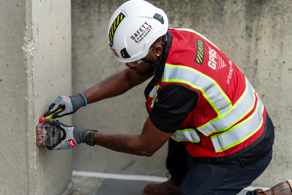
Understanding Post-Tensioned Construction Near Columns
Post-tensioned slabs contain steel tendons that are tensioned after the concrete has hardened.
Concrete is weak in tension and strong in compression. A slab has tension points at the bottom of the slab between the beams and column lines and has tension at the top of the slab at the beams and/or column lines.
Steel is very strong in tension. Combining steel reinforcing with concrete takes advantage of the strengths of both materials. But their strengths can be taken advantage of in an even greater way by actively putting the steel into tension by using post tension cables.
Tensioning the cables also puts the concrete into compression, which is its strongest state.
By draping the cables over the column lines, the tension in the concrete is counteracted in the appropriate places. When the cables are tensioned, they will be trying to lift up when they are at the bottom of the slab, which will provide support where the slab is trying to sag downward. The cables will also be pushing down when they are high in the slab and counteracting the tension at the top of the slab due to the columns and/or beams.
The post tension tendons run through ducts in the slab and are stressed to extremely high levels—often between 33,000 and 43,000 pounds of force per tendon (lbf/tendon or lbs/tendon).
Post tension cables are typically encased in a grout sheath, which is a cementitious material that fills the space around the steel strands. This material acts as a physical barrier protecting the steel strands from water, oxygen, and carbon dioxide – and therefore, preventing corrosion.
The use of PT cable allows for thinner slabs and eliminates the need for support beams and therefore allows for more vertical space. It also frees up designers to create more uniquely shaped concrete slabs, ramps, curves, and more.
But cutting or nicking even one PT cable can release its stored energy in a sudden and dangerous burst. In some cases, severed cables have shot out of the concrete, causing injuries or property damage.
Columns, being primary load-bearing elements, are focal points for tendon congestion. More tendons typically converge near columns than in other areas of the slab, making the risk of accidentally cutting one significantly higher. Columns are also often surrounded by stirrups, rebar, and embedded utilities, creating a dense web of potential hazards that cannot be detected with the naked eye.
The Dangers of Improper Cutting
Cutting or coring without hiring a professional concrete imaging company like GPRS to clear locations near a column in a PT slab can have serious consequences. Here are some of the most critical risks:
- Severing Post-Tension Tendons: This can result in sudden cable recoil, injuries, expensive repairs, and structural compromise.
- Damaging Rebar: Rebar is essential for slab integrity. Damaging it may weaken the area around the column, which is already under heavy load.
- Cutting Through Embedded Utilities: Electrical conduit, plumbing, and HVAC lines are often embedded in slabs. Accidental damage can cause delays, fires, or flooding.
- Structural Instability: A column is a load path. Damaging structural elements near it can lead to settlement, cracks, or even partial collapse in severe cases.
- Code Violations and Liability: Building codes typically require scanning in PT slabs before any cutting or coring. Skipping this step can result in fines, legal liability, and insurance claims.
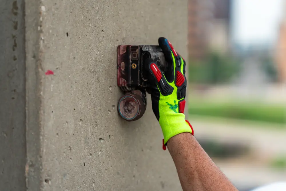
The Role of Professional Concrete Scanning
This is where professional concrete scanning companies like GPRS step in. We utilize ground penetrating radar (GPR) and other complimentary technologies to clear safe cutting and coring locations not only around columns, but wherever you need to work along a concrete slab.
GPR scanners emit radio waves into a slab, then detect the interaction between those waves and any embedded objects like post tension cable, rebar, or conduit. Those interactions are then displayed in a readout as a series of hyperbolas, which vary in size and shape depending on what type of obstruction was located.
GPRS Project Managers are specially trained to interpret this data to tell you what was located and provide the approximate depth of those objects.
GPR is fast, safe, and accurate. Unlike concrete X-ray, which require access to both sides of the slab and poses radiation hazards, GPR can be used from one side and poses no health risks. It’s highly effective even in congested areas near columns and can identify the approximate depth and orientation of structural elements.
The Process: What to Expect When GPRS Scans Your PT Slab
When you hire GPRS to scan a PT slab near a column, we’ll follow our standard process for precision concrete scanning:
- Initial Assessment: A site visit to understand the scope of the work and identify areas of concern.
- Surface Preparation: Cleaning the surface for optimal GPR signal penetration.
- Scanning: Using handheld GPR units, our Project Manager will scan the target area. We perform long scans across the slab to identify the bottom of the slab, reinforcing pattern, PT cable pattern, and type of slab. If space is limited, we’ll move to open areas to perform long scans to understand these patterns before moving back to the project area. For slab-on-grade projects, we’ll also check our work with a passive sweep of an electromagnetic (EM) locator looking for any conduits in the area.
- Marking the Slab: Safe cutting and coring zones are clearly marked with green boxes on the surface using paint or chalk. Tendons, rebar, and utilities are color-coded for easy identification.
- Reporting: GPRS Project Managers leave you with detailed scan reports, complete with images and notes, which can be archived for future reference or shared with engineers and contractors. And all this data is uploaded into SiteMap® (patent pending), our interactive infrastructure mapping platform that provides accurate existing conditions documentation to protect your assets and people.
- On-Site Consultation: Our Project Manager will walk through the findings with your team, answering questions and making recommendations. If your initial cutting or coring locations are determined to be unsafe, we’ll suggest alternative locations that are clear of buried obstructions.
Why Experience Matters
While GPR technology is powerful, its effectiveness depends heavily on the skill of the technician using it. Reading and interpreting the images produced by GPR requires training and hands-on experience. PT tendons and rebar, for example, can produce similar signatures – and a misread can lead to unsafe cuts.
That’s why it’s essential to hire a specially trained, experienced concrete scanning company like GPRS, which adheres to the Subsurface Investigation Methodology (SIM).
Benefits of Hiring a Professional Scanning Company Like GPRS
- Enhanced Safety: Prevent accidents, injuries, and unplanned structural issues.
- Reduced Liability: Documented scans demonstrate due diligence, which can be critical in legal or insurance claims.
- Cost Savings: Avoid expensive repairs and downtime by getting it right the first time.
- Improved Project Scheduling: Fast, efficient scanning allows you to stay on track without unnecessary delays.
- Peace of Mind: Knowing that your work area is safe means fewer surprises and smoother execution.
Don’t Cut Corners Near Columns
Post-tensioned concrete offers a host of structural advantages—but it demands respect, especially near load-bearing elements like columns.
Cutting or coring in these high-risk areas without first having proper scanning completed can have disastrous consequences. A single severed tendon can jeopardize not only the structure, but also the safety of everyone on site.
GPRS Concrete Scanning Services ensure that you’re making informed decisions, protecting your team, and delivering high-quality work that stands the test of time.
What can we help you visualize?
Frequently Asked Questions
How is GPR used to identify tendons vs. rebar in a post-tensioned slab?
In post-tensioned structures, we typically find one mat of support rebar near the base of the slab. This mat is generally consistently spaced and remains at a constant elevation. Post-tension cables are generally found above this support mat and “draped” throughout the rest of the structure. The elevation of the cable is usually high near the beams and column lines and drapes lower through the span between beams and column lines. Knowledge of these structural differences allows us to accurately differentiate between components. Our Project Managers will leave you feeling confident in our findings and in your ability to drill or cut without issue.
Can GPR determine the difference between rebar and electrical conduit?
Ground penetrating radar can accurately differentiate between rebar and electrical conduit in most cases. We have an extremely high success rate in identifying electrical lines in supported slabs or slabs-on-grade before saw cutting or core drilling.
Additionally, GPRS can use EM locators to determine the location of conduits in the concrete. If we can transmit a signal onto the metal conduit, we can locate it with pinpoint accuracy. We can also find the conduit passively if a live electrical current runs through it.
The combined use of GPR and EM locating allows us to provide one of the most comprehensive and accurate conduits locating services available.
NAVIGATING NYC’s LOCAL LAW 97 FOR ARCHITECTS & ENGINEERS

The City of New York updated Local Law 97 (LL 97) in December of 2024. Here’s a quick overview of what you need to know:
- Low-income landlords get a break with the new Affordable Housing Reinvestment Fund to provide electrical retrofits for affordable housing. The purchasing offsets it generates give building owners the ability to comply with the law and reduce emissions in affordable housing in the city.
- Facilities Managers may be pleased to see amended greenhouse gas calculations for campus systems, and alternative compliance processes for some cogeneration systems already in place.
- Historical preservationists, architects, and engineers may applaud the revisions that include adjustments on emissions limits for buildings with legal, physical, or financial constraints – “providing much needed detail” on the methodology on why and how adjustments may be granted.
- The final pillar of the December 2024 update sets fees for submissions on emissions reports and other applications so owners are clear on the up front reporting and application costs.
------------------------------------------------------------------------------------------------------------------------------------------------------------------------
GPRS helps stakeholders and contractors come into compliance with ESG goals and Local Law 97 with a wide variety of products and services – from 2-6mm accurate 3D laser scans and deliverables of the most complex historical spaces to the immediately actionable subsurface utility map data you need before breaking ground, to 99.8% accurate concrete scanning and imaging before you cut, core, or drill, GPRS can help you meet LL97’s requirements faster, easier, and more safely. Learn more about GPRS, here.
-------------------------------------------------------------------------------------------------------------------------------------------------------------------------
Where Does Rule Update Three Fall in the Scope of LL97?
This is the third major rule addition to LL97 since it was enacted in 2019. The previous rule additions took place in December 2022 and December 2023. The 2022 goals were to establish greenhouse gas emissions for structures over 25,000 s.f., require annual emissions reporting to the New York Department of Buildings, and laid out penalties for excess emissions.
2023’s rule additions sought to loosen some of the 2022 standards by allowing for referred compliance, defining “good faith efforts” to comply, and allowed building owners to apply for an extension on their emission limits till 2026.
How it Began – Enacting LL97
New York City's Local Law 97 (LL97), enacted in 2019 as part of the Climate Mobilization Act, mandates significant reductions in greenhouse gas (GHG) emissions from large buildings. Targeting structures exceeding 25,000 square feet, LL97 aims for a 40% reduction in emissions by 2030 and an 80% reduction by 2050, relative to 2005 levels.
Applicability and Compliance Thresholds
LL97 applies to:
• Buildings over 25,000 gross square feet
• Multiple buildings on a single tax lot collectively exceeding 50,000 square feet
• Condominium complexes governed by the same board, with combined areas surpassing 50,000 square feet
• Exemptions include industrial facilities, certain residential properties, and specific nonprofit organizations
Emission Limits and Compliance Periods
The law establishes emission intensity limits (measured in kilograms of CO₂ equivalent per square foot) based on building occupancy classifications. The initial compliance period spans 2024 to 2029, with stricter limits commencing in 2030. For example, residential buildings (Group R-2) have a limit of 6.75 kgCO₂e/sq ft for 2024–2029, tightening to 4.07 kgCO₂e/sq ft for 2030–2034.
What is LL97's Impact on Construction Projects?
For architects and engineers, LL97 necessitates integrating energy efficiency and low-carbon strategies into both new constructions and renovations:
• Design Considerations: Incorporate high-performance building envelopes, advanced HVAC systems, and energy-efficient lighting to minimize energy consumption.
• Electrification: Transition from fossil fuel-based systems to electric alternatives, such as heat pumps, to align with the city's decarbonization goals.
• On-Site Renewable Energy: Implement solar photovoltaic systems or other renewable technologies to offset building emissions.
These measures not only ensure compliance but also enhance building performance and occupant comfort.
Penalties for Non-Compliance
Buildings exceeding emission limits face financial penalties calculated at $268 per metric ton of CO₂ equivalent over the threshold. Failure to submit required reports incurs fines of $0.50 per square foot per month, and falsifying reports can result in penalties up to $500,000.
Flexibility Measures and Extensions
Recognizing the challenges in meeting these requirements, the city offers flexibility mechanisms:
- Good Faith Efforts: Building owners demonstrating earnest attempts to comply may receive extensions. This involves submitting a decarbonization plan by May 1, 2025, detailing strategies to meet emission limits by 2026 and outlining long-term plans for 2030 compliance.
- Renewable Energy Credits (RECs): Owners can purchase RECs to offset emissions, though reliance solely on RECs without implementing on-site reductions is discouraged.
Recommendations for Architects and Engineers
To navigate LL97 effectively:
- Early Integration: Embed energy modeling and sustainability assessments at the project's inception to identify cost-effective compliance strategies.
- Collaborative Approach: Engage multidisciplinary teams, including sustainability consultants and MEP (mechanical, electrical, plumbing) engineers, to develop holistic solutions.
- Stay Informed: Regularly update knowledge on evolving regulations, technological advancements, and best practices in sustainable design.
By proactively addressing LL97's mandates, professionals can lead in creating resilient, efficient, and compliant urban environments.
Additional Resources for Building Owners Include:
NYC Department of Buildings' Guidelines on greenhouse gas emissions
Understanding and implementing LL97 is pivotal for the future of sustainable construction in New York City. Architects and engineers play a crucial role in this transition, ensuring that the built environment contributes positively to the city's climate objectives.
Frequently Asked Questions
What is ESG and how does it impact greenhouse gas emissions?
ESG in facilities and construction refers to the integration of Environmental, Social, and Governance principles into planning, design, construction, and operational practices. It emphasizes sustainable resource use, carbon reduction, worker safety, community impact, ethical procurement, and regulatory compliance. ESG frameworks guide decision-making to minimize environmental harm, promote social responsibility, and ensure transparent governance. In this sector, ESG is essential for risk management, long-term asset value, and alignment with investor and regulatory expectations. Learn more about ESG, here.
How do GPRS' services support net zero and greenhouse gas reduction construction?
GPRS works closely with facilities managers, architects, engineers, and general contractors to support their sustainable building goals. Our suite of above and below-ground infrastructure data capture tools provide project managers, designers, builders, and stakeholders the peace of mind they need to work more efficiently, streamlining communication and collaboration by providing secure, shareable interactive utility maps, structural data, and existing conditions records via SiteMap® (patent pending), our GIS and project management software platform. Every GPRS customer receives complimentary SiteMap® Personal access, and we offer a variety of digital management solutions for virtually every industry. To learn more about GPRS and SiteMap®, click here.
What is Iron Air Battery Technology & Does it Provide a Viable Lithium-Ion Alternative for The Renewable Energy Market?
In the fall of 2021, The Wall Street Journal wrote a piece on Form Energy, a renewables technology company who claimed they’d made a “breakthrough in long-duration batteries” that were poised to go head to head with lithium-ion (LIB) storage for renewable energy grid projects. Their investors, including a who’s-who of technology innovators like Bill Gates and Jeff Bezos, are banking on Form’s ability to build, “the kind of battery you need to fully retire thermal assets like coal and natural gas power plants.” That’s how Form’s CEO, former Tesla Powerball developer, Mateo Jaramillo describes their new Iron Air batteries.
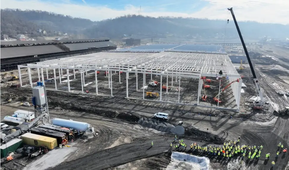
Four years later, we’re about to find out if Form’s Iron Air technology lives up to the hype because their West Virginal production facility is producing their “grid-scale” storage solution in anticipation of their first U.S. battery storage system. Their investors now include GE Verona, MIT’s Engine Ventures, and Energy Impact Partners, according to reporting in Engineering News-Record. The initial installation will be in a converted paper & pulp mill in Lincoln, Maine. At 8,500MW, it is expected to be “the largest battery project by energy storage capacity in the world,” according to a Form spokesperson.
Minnesota’s Great River Energy is constructing a 1.5MW Form Energy system project that is expected to go online at the end of 2025, and three more Form storage systems, two 10MW projects for Excel Energy and a 15MW facility for Georgia Power are projected for 2025 and 2026 online dates.
-----------------------------------------------------------------------------------------------------------------------------------------------------------------
GPRS’ work supports green power and renewable energy projects throughout the United States. Learn more about our work in the wind, solar, geothermal, and hydrothermal energy sectors, here.
-----------------------------------------------------------------------------------------------------------------------------------------------------------------
What is an Iron Air Battery?
Before delving into how Iron Air battery technology works, it’s worthwhile to remember, first, how LIB technology works, since it is the current king of the renewable energy hill.
A Refresher on Lithium-Ion Battery Technology
Lithium-ion batteries store and release energy by shuttling lithium ions between two electrodes – anode and cathode – through an electrolyte. Their high energy density, efficiency, and perceived long cycle life make them the most popular option for storing energy. This is the same technology that is used in EVs, cell phones, and a plethora of chargeable electronic devices.
LIB technology has proven scalable, and at the grid scale, has been a successful storage solution for intermittent renewable energy, making it the storage system of choice for renewables like solar and wind energy.
However, that high energy density does come with risk, especially at scale. Thermal runaway is the term used to describe the chain-reaction-like combustion that occurs on the rare occasion that a lithium-ion array catches fire. Thermal runaway is considered so dangerous, due to both its toxicity and extreme temperatures, that the International Association of Fire Chiefs “strongly advises” that no firefighter enter an LIB facility fire location.
Iron Air Battery Technology Explained
At its simplest, Iron Air technology operates on a concept Form Energy calls “reversible rusting.”
The cycle is deceptively simple:
• When the Iron Air battery is discharging its energy, the battery “breathes in” oxygen and converts its iron metal (stored inside the battery in pellets the size of musket balls) to rust
• When the battery is charging, the electrical current applied while it’s storing up energy converts the iron rust back into iron as the battery “exhales” oxygen
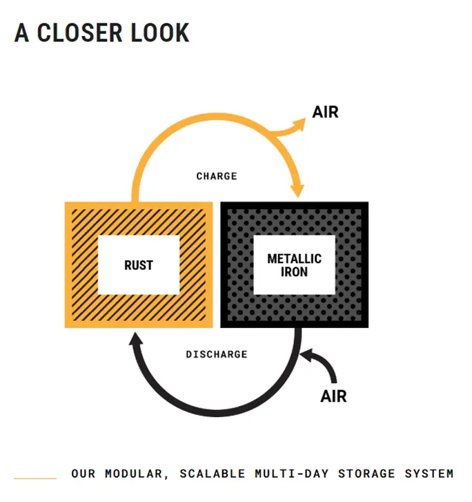
Photo Credit: Form Energy
"When a building rusts or a bridge rusts, it is very slowly discharging [energy]," Jaramillo explained. Form's batteries can reverse the rusting process with the addition of electric current, turning rust back to iron and releasing oxygen. When the energy is needed, the battery takes in oxygen, rusting the iron and releasing some energy.
"What we have done is build a device that takes that reaction and harnesses it and lets us manufacture that battery and deploy it in very large volumes," Jaramillo told Newsweek in late 2024.
While critics may decry Iron Air’s size – about the size of a standard washer/dryer set in the U.S., containing stacks of about 30, meter-tall cells while lithium-ion technology can be much smaller – no one is trying to put Iron Air into cars or smartphones. These are giant batteries, designed to store and discharge large quantities of energy at grid scale.
Plus, Iron Air batteries are reportedly significantly less expensive to produce and operate. With an average cost of just $6 per KW, this emerging technology offers a significant increase in storage duration, and the base conductive material, iron, is “abundant, nontoxic, and nonflammable,” unlike the chain-reaction thermal runaway combustion of an LIB.
For those in the renewable energy industry, Iron Air battery storage systems could prove to be the missing link in the expansion and modernization of the U.S. power grid. Whether they live up to being a tool that helps move power generation and transmission away from fossil fuels remains to be seen.
GPRS Intelligently Visualizes The Built World® for customers in the power, renewables, and oil and gas industries.
What can we help you visualize?
Frequently Asked Questions
Is GPRS able to support projects on a national scale?
The short answer is YES! GPRS has a nationwide army of highly trained, SIM-certified Project managers that spans the entire U.S., including Alaska, Hawaii, and even Puerto Rico. We are regularly called on to provide support for large projects in the energy sector, retail, environmental, healthcare, education, infrastructure, and a wide variety of industries associated with architecture, engineering, and construction.
Learn more about GPRS’ nationwide footprint, here.
How does GPRS deliver its data on large regional, or national projects?
Whether your job is a single utility locate or a thousand miles of lines, GPRS takes great care to deliver the same standardized, high level of service and deliverables to every customer. That’s why we developed SiteMap® (patent pending), our industry-leading, interactive software platform. Every GPRS customer receives complimentary SiteMap® Personal access, and we have the capability to build customized SiteMap® solutions that cover the scope of a single construction site, all the way up to a national facilities portfolio. To learn more about what SiteMap® can do for your project, click here.